
B
Brandi MannJul 31, 2025
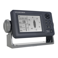
How to fix Furuno SC-130 if it cannot turn the power on?
- GGina CunninghamJul 31, 2025
If your Furuno Compass won't power on, several factors could be at play. First, examine the power cables for any signs of corrosion or damage, and replace them if necessary. Next, ensure the power cable connections are securely fastened. Also, check the fuses; if they're blown, contact your dealer for replacements. Finally, verify that the ship's battery voltage is within the appropriate range.