1. INSTALLATION
1-20
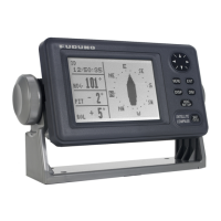
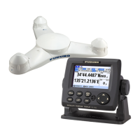
1.5.6 How to connect the Display unit (SC-702)
The display unit is connected to the Junction Box using a 9-pin WAGO connector. Re-
ferring to section 1.5.3 and the table below, fabricate the WAGO connector. Note that
the WAGO connector is included inside the SC-702 and must first be removed from
the unit.
1. Unfasten the four screws on the rear cable clamp of
the SC-702, then remove the cable clamp to reveal
the WAGO connector.
2. Unplug the WAGO connector from the SC-702.
3. Pass the cable through the cable clamp.
For the supplied cable (Z-#26X2P+0.3SQX1PL)
When the supplied cable is used, the supplied cable gasket (Type: 20-037-2104-
0) must be attached. Open the cut line of the cable gasket then attach the cable
gasket to the cable.
Note: To prevent water intrusion, the cut line of the cable gasket must face down-
ward.
4. Referring to the following table and the interconnection diagram at the back of this
manual, connect the cable to the WAGO connector.
Display unit (SC-702) internal J301 WAGO connector (9-pin, TTYCSLA-4)
5. Connect the cabling to the SC-702.
6. Slide the clamp along the cable towards the SC-702, then fasten the four screws
which were removed at step 1.
Pin
no.
Connection
(signal)
Description Remarks
1 P12V Power -
2 GND Grounding.
Connect to SC-701.
-
3-
4-
5 TD_A TX data Fixed at 115200 bps.
6 TD_B TX data
7 RD_A RX data
8 RD_B RX data
9 GND Drain wire Connect to drain wire.
WAGO
connector
Cable
clamp
 Loading...