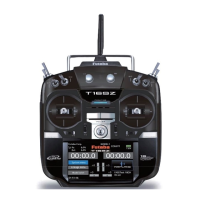
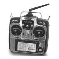
24
<Before Use>
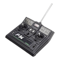
Link/Mode Switch
Use the small plastic screw driver that was
included with your receiver.
The Link/Mode Switch is also used for the CH
mode selection.
Extra Voltage Connector
Use this connector when using a voltage
telemetry device to send the battery voltage (DC0
a9IURPWKHUHFHLYHUWRWKHWUDQVPLWWHU
<RXZLOOQHHGWRSXUFKDVHWKHRSWLRQDO([WHUQDO
9ROWDJHLQSXWFDEOH&$59,1)870
<RXFDQWKHQPDNHDFDEOHZLWKDQH[WUD
connector to the External voltage connector.
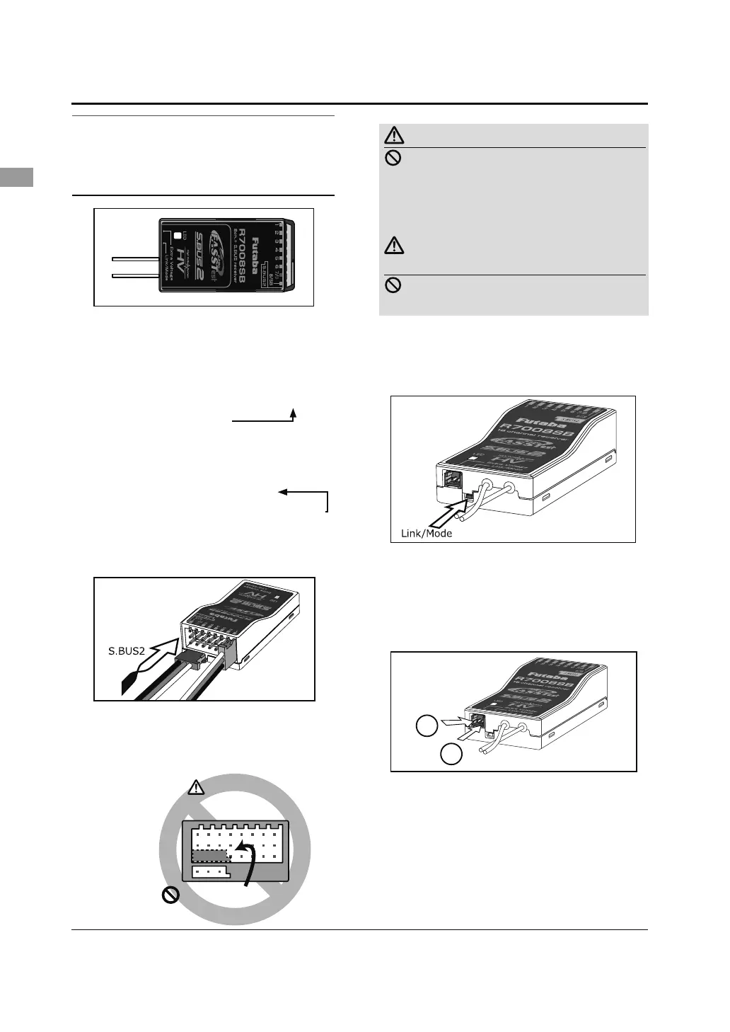
Receiver nomenclature
Before using the receiver, be sure to read the
precautions listed in the following pages.
Receiver R7008SB
Connector
"1 through 6": outputs for the channels 1
through 6
%RXWSXWVRIFKDQQHOVDQGSRZHU
"8/SB": outputs of 8 channels or S.BUS port.
[S.BUS Servo S.BUS Gyro ]
*When using 8/SB as S.BUS, you have to set
CH MODE of the following page to mode B or
mode D.
"S.BUS2": outputs of S.BUS2 port.
[S.BUS2 Servo S.BUS2 Gyro Telemetry Sensor ]
*When using 9 or more channels, use an S.BUS
IXQFWLRQRUXVHDVHFRQG56%DQGOLQNERWK
to your transmitter.
Connector insertion
Firmly insert the connector in the direction
VKRZQLQWKH¿JXUH,QVHUWWKH6%86E\WXUQLQJ
it 90 degrees.
+
−
Do not connect either a switch
or battery in this manner.
5HFHLYHU
Danger
Danger
Don't connect a connector, as shown in a
EHIRUH¿JXUH
*It will short-circuit, if it connected in this way. A short
circuit across the battery terminals may cause abnormal
KHDWLQJ¿UHDQGEXUQV
Warning
S.BUS2 connectors
Don't connect an S.BUS servo / gyro to
S.BUS2 connector.
LED Monitor
This monitor is used to check the CH mode of
the receiver.