32
<Before Use>
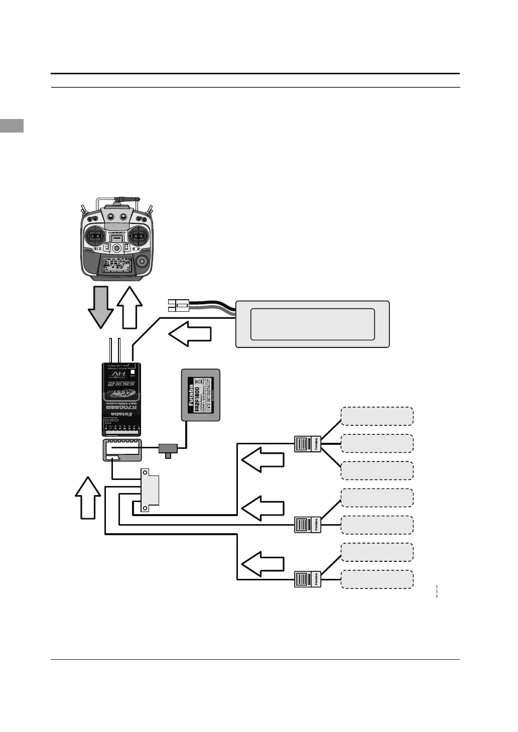
Telemetry System
7KH56%UHFHLYHUIHDWXUHVELGLUHFWLRQDOFRPPXQLFDWLRQZLWKD)$667HVW)XWDEDWUDQVPLWWHUXVLQJ
the S.BUS2 port. Using the S.BUS2 port an impressive array of telemetry sensors may be utilized. It also
includes both standard PWM output ports and S.BUS output ports.
* Telemetry is available only in the FASSTest 14CH mode. (12CH mode displays only Receiver battery
voltage and Extra battery voltage.)
7KHWHOHPHWU\IXQFWLRQUHTXLUHVWKHFRUUHVSRQGLQJUHFHLYHU56%
7KH76*ZLOOHQWHUDQGNHHSWKH,'QXPEHURIWKH56%WKDWLWLVOLQNHGWR
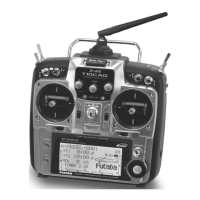
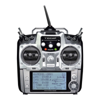
76*
●Telemetrysensor(soldseparately)
Your aircrafts data can be checked in the
transmitter by connecting various telemetry
sensors to the S.BUS2 connector of the
receiver.
●SlotNo.
Servos are classified by channel, but sensors
are classified by “slot” . Since the initial slot
No. of the T14SG is preset at each sensor,
the sensors can be used as is by connecting
them. There are 1
~
31 slots.
6%86
&RQQHFWRU
7HPSHUDWXUH
6HQVRU
Slot1
Slot2
Slot3 〜 5
Slot6 〜 7
Slot8 〜 15
Slot16
Receiver
Batteryvoltageis
displayedatthetransmitter.
Powerbatteryvoltageis
displayedatthetransmitter.
6ZLWFK
7HUPLQDOER[
+8%
+8%
+8%
Info
Info
Info
Info
Info
voltage
Signal
530
6HQVRU
$OWLWXGH
6HQVRU
*36
6HQVRU
Slot17
Slot31
6HQVRU
9ROWDJH
6HQVRU
6HQVRU
Info