Wire these signal wires to the DSUB9 connector of the I/O cable by referring to the following.
* At least the trigger signal must be wired (Close Mold signal etc.) to continuously monitor the pressure
waveforms in the mold.
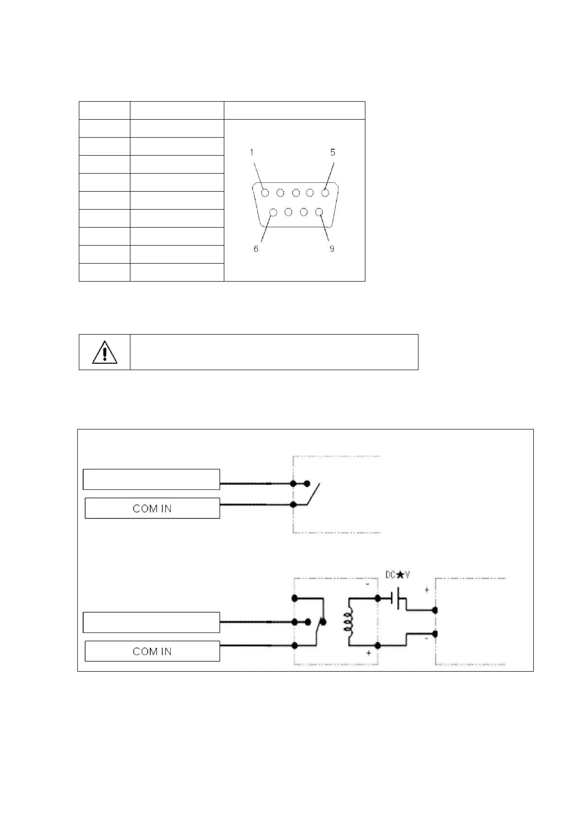
●DSUB9 connector pin connections
●Input signal circuit specifications (trigger signal, clear alarm signal)
Input the signal to the amplifier via the electromechanical relay.
Do not apply voltage.
Example 1: When the output of the molding machine connected to the amplifier is “relay output”
Example of connection of input signal when the molding machine output signal is contact output
Molding machine output signal
Molding machine
output signal