8A089X01 Rev 1
SLIM Installation Manual
3/23/2018 Page 24 of 61
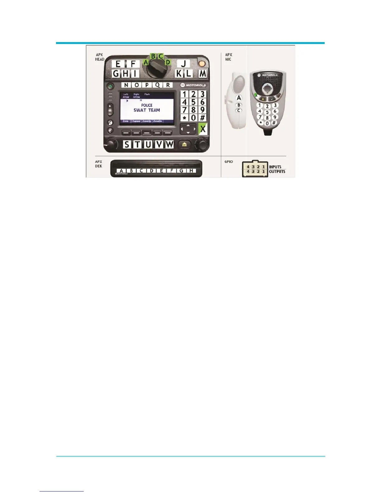
Figure 2-21 Input/Output Identification
The labeling on each device’s image is used to identify the button in the configuration.
Generally, the labels are specific to the piece of hardware. For example, “A” on the O9
control head is unique and separate from “A” on the DEK, or from “A” on the keypad mic.
These input buttons are unique on each device or accessory. However, the numeric
keypad is not unique between devices. The number “1” on the O9 control head is the same
number “1” on the keypad mic. This is a feature of the radio. Users familiar with the radio
CPS are already familiar with the shared keypad functionality.
The GPIO pins are located on the physical GPIO port of the Module. There are four
dedicated inputs and four dedicated outputs. The inputs are treated the same as any other
button but are ground activated rather than being physically pressed. For electrical
information refer to Section 3.4.5: “General Purpose Inputs & Outputs (GPIO)”.