8A089X01 Rev 1
SLIM Installation Manual
3/23/2018 Page 19 of 61
2.4.2 Power the Module
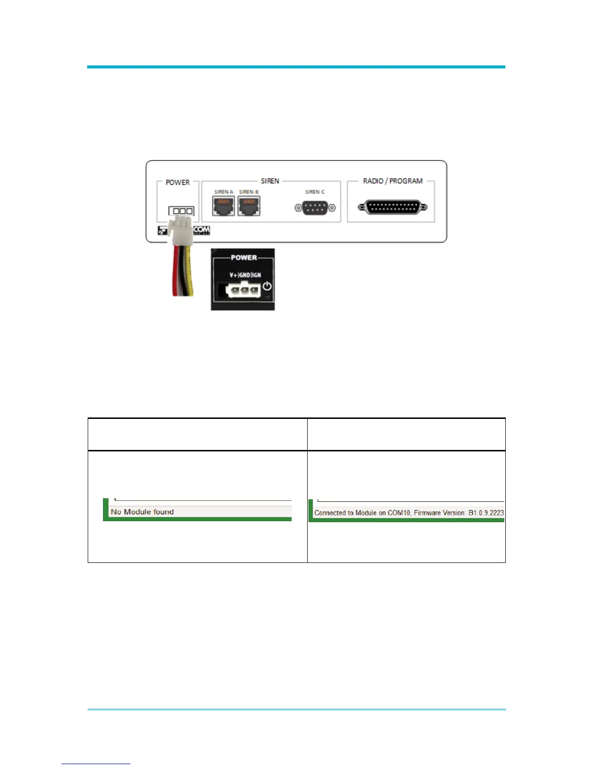
After connecting the programming cable, power up the Module. Connect the Module’s
power harness to a 12V DC or compatible power source, and then connect the power
harness to the Module. The V+ (red) and Ignition (yellow) leads will both need to be
connected to the same positive voltage source during programming to ensure the Module
is powered on. Please refer to the Section 3.4: “Wiring” for additional wiring details.
Figure 2-12 Power Harness Connection
2.4.3 Programming Utility
Open the Module’s Programming Utility on the PC that the Module is connected to. When
properly connected, a successful status message will be displayed in the lower left corner
of the utility. If the module is not connected properly, an error message will be displayed
in the lower left corner of the utility.