34 • Chapter 4 Communication DMC-1000
996-512=484
4. Convert result from above into binary.
484=1 1 1 1 0 0 1 0 0
2
8
2
7
2
6
2
5
2
4
2
3
2
2
2
1
2
0
5. Let switches A2 through A8 represent bits 2
2
through 2
8
of above,
Where ON= 0, OFF=1
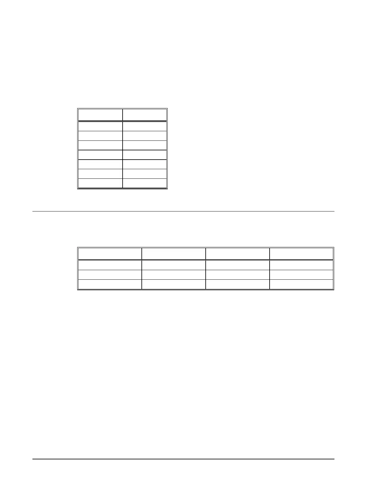
Switch Position
A2 OFF
A3 ON
A4 ON
A5 OFF
A6 OFF
A7 OFF
A8 OFF
Note: The appendix contains a table with the proper switch setting for all possible addresses.
Communication with the Controller
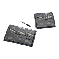
Communication Registers
Register Description Address Read/Write
READ for receiving data N Read only
WRITE for transmitting data N Write only
CONTROL for status control N+1 Read and Write
The DMC-1000 provides three registers used for communication. The READ register and WRITE
register occupy address N and the CONTROL register occupies address N+1 in the I/O space. The
READ register is used for receiving data from the DMC-1000. The WRITE register is used to send
data to the DMC-1000. The CONTROL register may be read or written to and is used for controlling
communication, flags and interrupts.
Simplified Communication Procedure
The simplest approach for communicating with the DMC-1000 is to check bits 4 and 5 of the
CONTROL register at address N+1. Bit 4 is for WRITE STATUS and bit 5 is for READ STATUS.
Artisan Technology Group - Quality Instrumentation ... Guaranteed | (888) 88-SOURCE | www.artisantg.com