DMC-1000 Chapter 7 Application Programming • 119
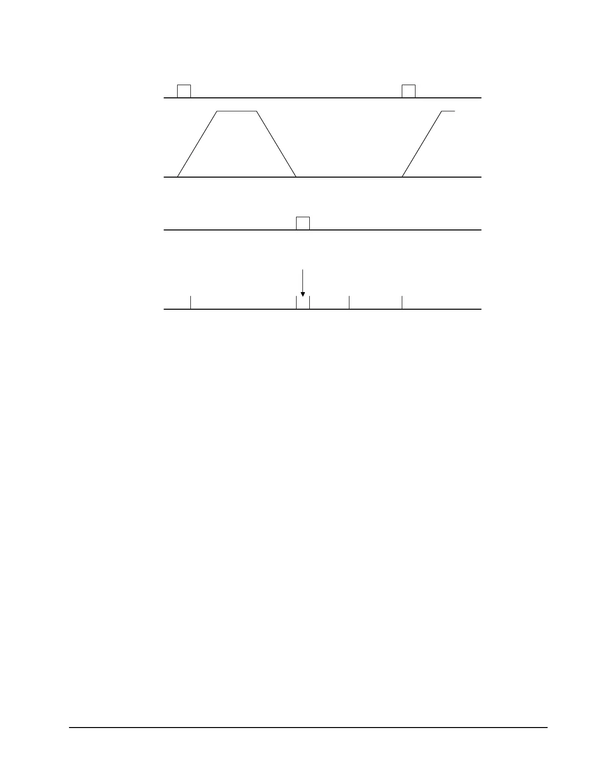
START PULSE I1
MOTOR VELOCITY
OUTPUT PULSE
TIME INTERVALS
move
output
wait ready move
Figure 7.1 - Motor Velocity and the Associated input/output signals
X-Y Table Controller
An X-Y-Z system must cut the pattern shown in Fig. 7.2. The X-Y table moves the plate while the Z-
axis raises and lowers the cutting tool.
The solid curves in Fig. 7.2 indicate sections where cutting takes place. Those must be performed at a
feedrate of 1 inch per second. The dashed line corresponds to non-cutting moves and should be
performed at 5 inch per second. The acceleration rate is 0.1 g.
The motion starts at point A, with the Z-axis raised. An X-Y motion to point B is followed by
lowering the Z-axis and performing a cut along the circle. Once the circular motion is completed, the
Z-axis is raised and the motion continues to point C, etc.
Assume that all of the 3 axes are driven by lead screws with 10 turns-per-inch pitch. Also assume
encoder resolution of 1000 lines per revolution. This results in the relationship:
1 inch = 40,000 counts
and the speeds of
1 in/sec = 40,000 count/sec
5 in/sec = 200,000 count/sec
an acceleration rate of 0.1g equals
0.1g = 38.6 in/s2 = 1,544,000 count/s
2
Note that the circular path has a radius of 2" or 80000 counts, and the motion starts at the angle of
270° and traverses 360° in the CW (negative direction). Such a path is specified with the instruction
CR 80000,270,-360
Further assume that the Z must move 2" at a linear speed of 2" per second. The required motion is
performed by the following instructions:
Instruction Interpretation
Artisan Technology Group - Quality Instrumentation ... Guaranteed | (888) 88-SOURCE | www.artisantg.com

 Loading...
