2 • Chapter 1 Overview DMC-1000
2. Step motors with step and direction signals
3. Other actuators such as hydraulics - For more information, contact Galil.
The user can configure each axis for any combination of motor types, providing maximum flexibility.
Standard Servo Motors with +/- 10 Volt Command
Signal
The DMC-1000 achieves superior precision through use of a 16-bit motor command output DAC and
a sophisticated PID filter that features velocity and acceleration feedforward, an extra pole filter and
integration limits.
The controller is configured by the factory for standard servo motor operation. In this configuration,
the controller provides an analog signal (+/- 10Volt) to connect to a servo amplifier. This connection
is described in Chapter 2.
Stepper Motor with Step and Direction Signals
The DMC-1000 can control stepper motors. In this mode, the controller provides two signals to
connect to the stepper motor: Step and Direction. For stepper motor operation, the controller does not
require an encoder and operates the stepper motor in an open loop fashion. Chapter 2 describes the
proper connection and procedure for using stepper motors.
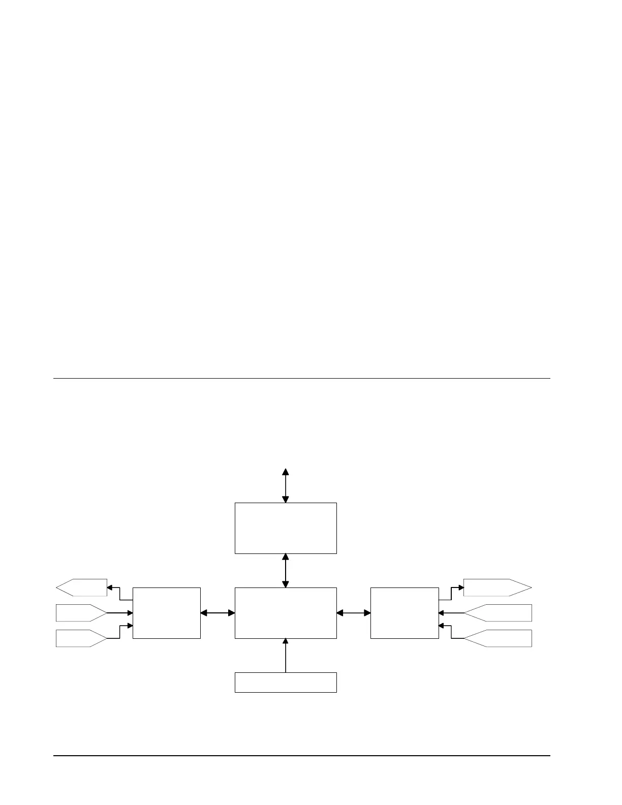
DMC-1000 Functional Elements
The DMC-1000 circuitry can be divided into the following functional groups as shown in Figure 1.1
and discussed in the following.
68331
Microcomputer
64K RAM
64K EPROM
256 EEPROM
I/O
Interface
GL-1800
4-Axes
Motor/Encoder
Interface
Communication
FIFO
512 Bytes
Watch Dog
Timer
8 Out
8 In
8 Analog In
To Host
To Amps
From
Limits
From
Encoders
Figure 1.1 - DMC-1000 Functional Elements
Artisan Technology Group - Quality Instrumentation ... Guaranteed | (888) 88-SOURCE | www.artisantg.com

 Loading...
