DMC-1000 Chapter 2 Getting Started • 5
Chapter 2 Getting Started
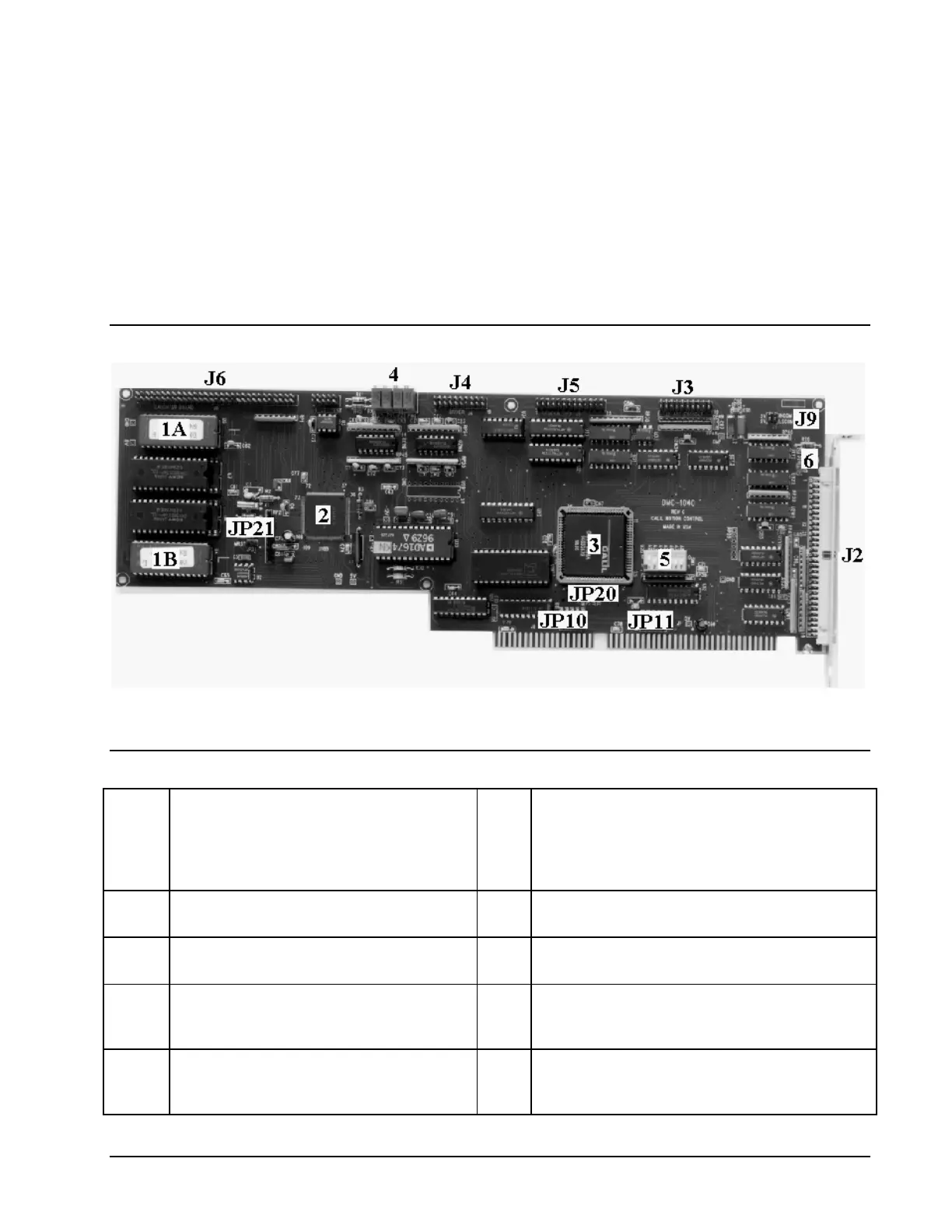
The DMC-1000 Motion Controller
Figure 2-1 - DMC-1000
1A/1B DMC-1000 ROM. These are labeled with
the firmware revision that you have
received. For example, a label may be
affixed to the ROM that specifies the
firmware revision such as ‘2.0c’.
J2 60-pin header connector for the main output
cable of the DMC-1000
2 Motorola 68331 Microprocessor J3 20-pin header connector for the auxiliary
encoder cable of the DMC-1000.
3 GL-1800 Custom sub-micron gate array J4 20-pin header connector for the stepper
amplifier output cable of the DMC-1000.
4 Calibration potentiometers to provide a
zero bias voltage to the amplifier for
proper operation.
J5 26-pin header connector for the general I/O
cable of the DMC-1000.
5 Address DIP switches J6 60-pin daughter board header connector for the
cable leading to the DMC-1050-1080, DB-10072
and DB-10096 I/O expansion boards.
Artisan Technology Group - Quality Instrumentation ... Guaranteed | (888) 88-SOURCE | www.artisantg.com