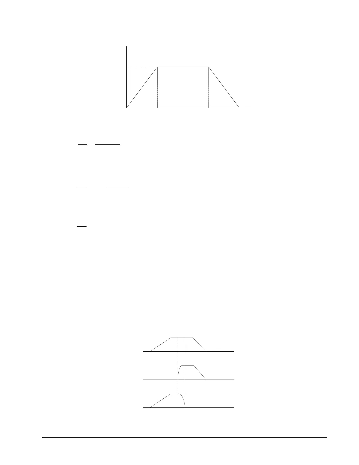
Figure 6.9: Vector Velocity Profile
The acceleration time, Ta, is given by
T
VS
VA
sa
100000
2000000
0 05.
The slew time, Ts, is given by
The total motion time, Tt, is given by:
The velocities along the X and Y axes are such that the direction of motion follows the specified path, yet the
vector velocity fits the vector speed and acceleration requirements.
For example, the velocities along the X and Y axes for the path shown in Figure 6.8 are given in Figure 6.10.
Figure 6.10 shows the vector velocity. It also indicates the position point along the path starting at A and ending at
D. Between the points A and B, the motion is along the Y axis. Therefore,
Vy = Vs
and
Vx = 0
Between the points B and C, the velocities vary gradually and finally, between the points C and D, the motion is in
the X direction.
Figure 6.10: Vector and Axes Velocities
Chapter 6 Programming Motion ▫ 73 DMC-41x3 User Manual
T
VS
T s
s
35708
0 0 307
D
a
100000
05
. .
0.05 0.357
10000
Velocity
time (s)
0.407T
a
T
a
T
s