Revision C 170 Series Monitor 5-5
2000947-004
Theory of Operation: Functional Overview
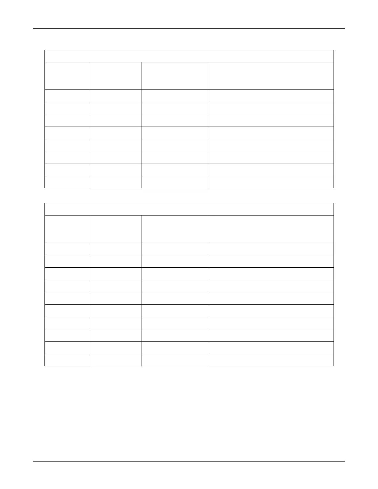
Table 5-3. Recorder Motor Connector
Pin Number Signal Name
Signal Type
(Relative to
Main board)
Signal Description
1 NC No Connection
2 P3 Output Motor Phase 3
3 P4 Output Motor Phase 4
4 +5VM Output +5 Volts for Motor
5 NC No Connection
6 P2 Output Motor Phase 2
7 P1 Output Motor Phase 1
8 +5VM Output +5 Volts for Motor
Table 5-4. Recorder Sensor Connector
Pin Number Signal Name
Signal Type
(Relative to
Main board)
Signal Description
1 NC No Connection
2 MISCOL Input Paper Misload Sensor Collector
3 MISLED Output Paper Misload Sensor LED Voltage
4 GND Output Ground for Sensor
5 NC No Connection
6 OUTCOL Input Paper Out Sensor Collector
7 OUTLED Output Paper Out Sensor LED Voltage
8 GND Output Ground for Sensor
9 DOOR Input Door Switch Input
10 GND Output Ground for Door Switch

 Loading...


