5-6 170 Series Monitor Revision C
2000947-004
Theory of Operation: Functional Overview
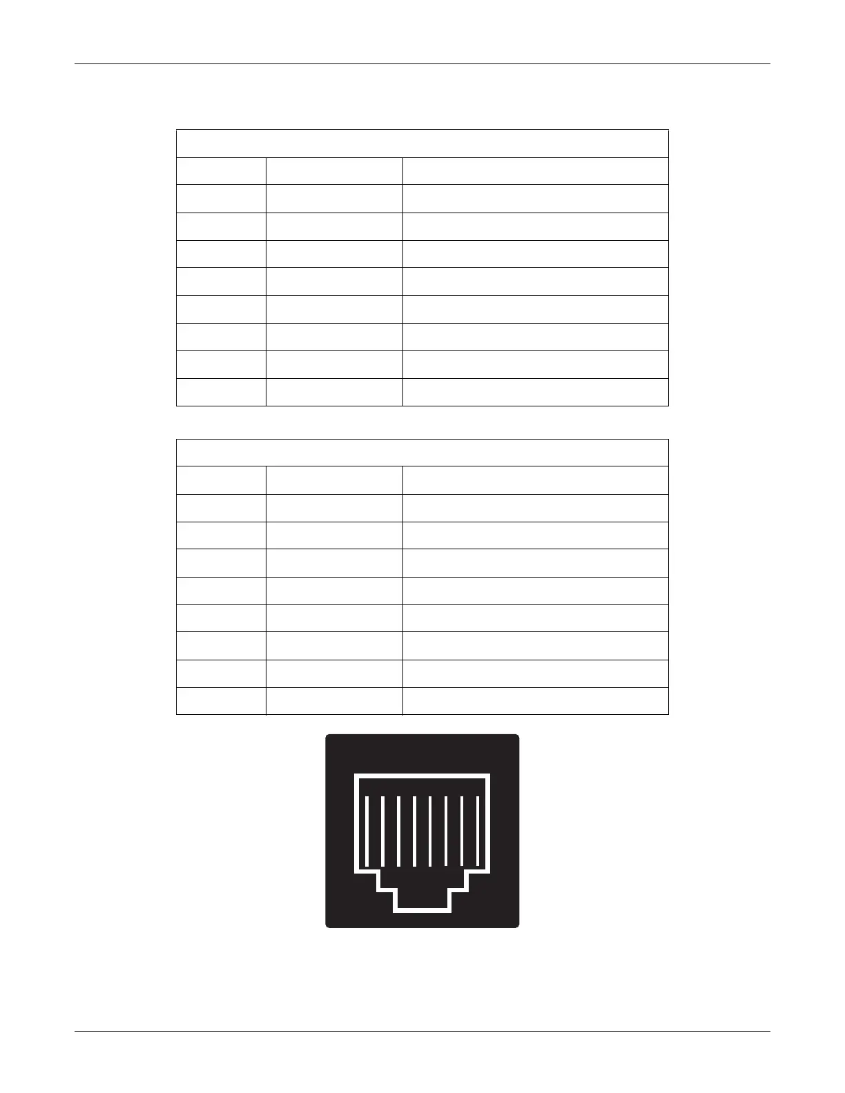
Figure 5-3. RJ-45 Connector (facing the rear panel from the outside)
Table 5-5. RS-232 Connector 1
Pin Number Signal Name Signal Description
1 +5V 200 mA Fused
2 RTS Request to Send Output from Monitor
3 RXD Receive Data Input to Monitor
4 GND Signal Ground
5 GND Signal Ground
6 TXD Transmit Data Output from Monitor
7 CTS Clear to Send Input to Monitor
8 +5V 200 mA Fused
Table 5-6. RS-232 Connector 2
Pin Number Signal Name Signal Description
1 GND Signal Ground
2 RTS Request to Send Output from Monitor
3 RXD Receive Data Input to Monitor
4 GND Signal Ground
5 GND Signal Ground
6 TXD Transmit Data Output from Monitor
7 CTS Clear to Send Input to Monitor
8 GND Signal Ground
1
2
3456
78

 Loading...


