106 GENERAL D400 SUBSTATION GATEWAY USER’S MANUAL
DUAL ETHERNET UPGRADE KIT WITH CARD 580-3410 CHAPTER 8: SERVICING THE D400
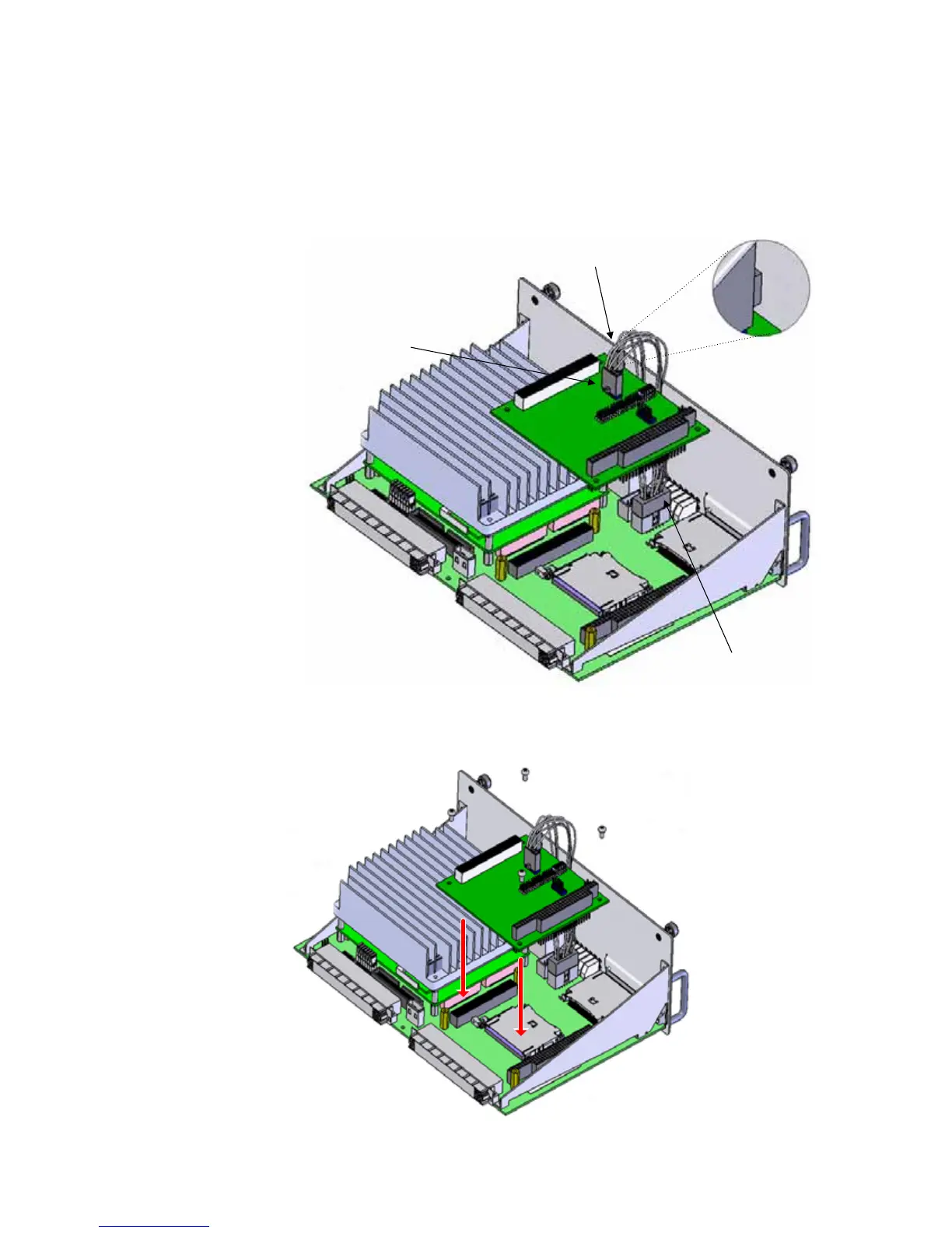
4. Plug the provided cable assembly (GE part number 975-0544) into connector LAN1
and LED1 on PC/104 card and connector P3 on the main board.
Note the proper orientation of LED1 connector polarity tab (nubbin facing out towards
the card edge), and the LAN1 connector polarity tab (nubbin facing in from the card
edge.
Figure 59: Dual Ethernet upgrade kit with card 580-3410 - cable connection
5. Attach the Ethernet Module card to the expansion slot and secure using the four
provided Philips screws.
Figure 60: Dual Ethernet upgrade kit with card 580-3410 - attach Ethernet module card
LAN1 connector
P3 connector
LED1 connector