38 GENERAL D400 SUBSTATION GATEWAY USER’S MANUAL
RS-485 ADAPTER CHAPTER 3: SETTING UP COMMUNICATION CARDS
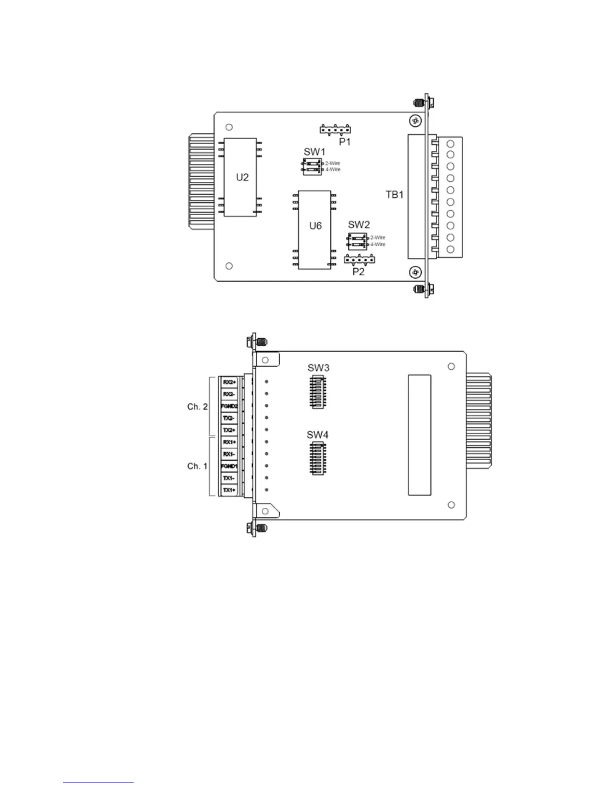
Figure 14: RS-485 Adapter Top Side)
Figure 15: RS-485 Adapter Bottom Side)
Switch SW3/SW4 configuration
Switches SW3 (for Channel 2 on TB1-6 through TB1-10) and SW4 (for Channel 1 on TB1-1
through TB1-5) contain ten DIP-switches that control RS-422 pull-up and pull-down
resistors for the differential data lines and provide line termination between the differential
data pairs. Each DIP-switch can be set to ON or OFF to select the appropriate function for
the switch. That is, if all pins are set to ON, switch is ON. If all pins are set to OFF, switch is
OFF.
If RS-422 termination/pull-up is selected, the TX+ and RX+ signals have a 680 ohm pull-up
resistor, the TX- and RX- signals have a 680 ohm pull-down resistor, and the RX and TX
signals have a 120 ohm termination.