64 GENERAL D400 SUBSTATION GATEWAY USER’S MANUAL
LOCAL HMI CONNECTION CHAPTER 4: CONNECTING TO DEVICES AND NETWORKS
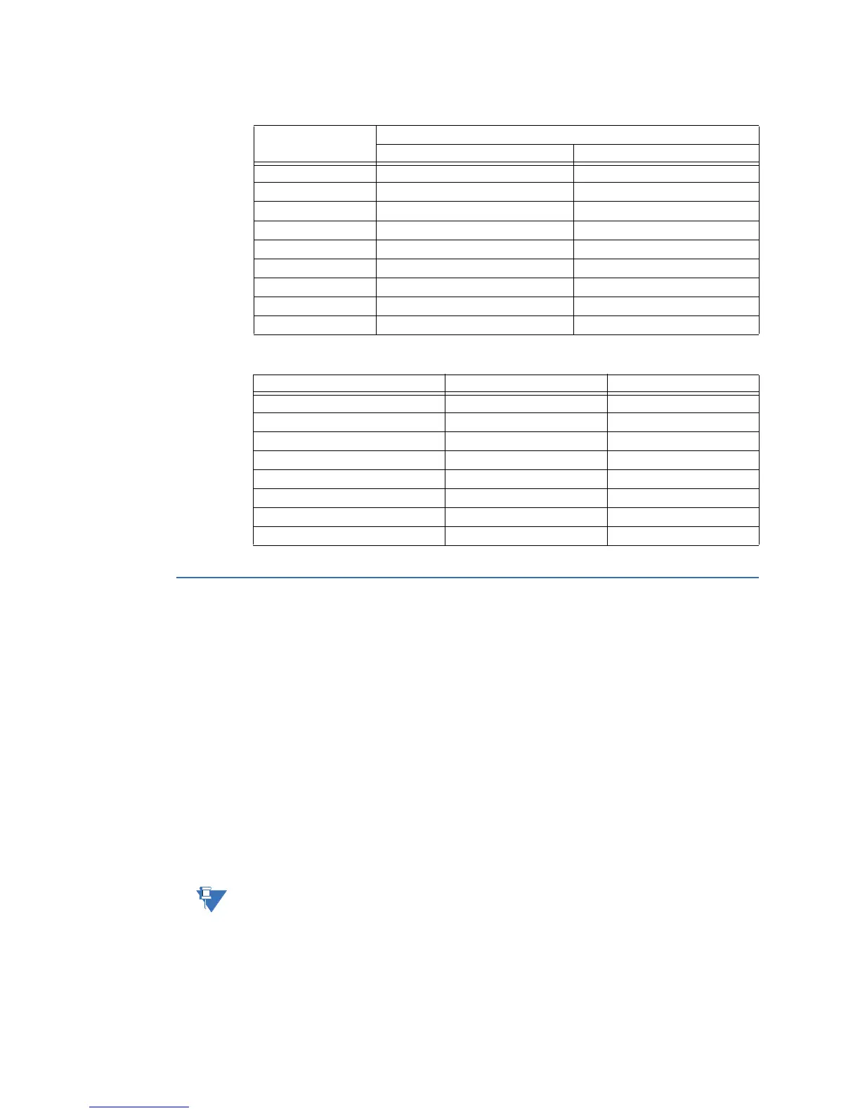
Table 18: COM2 Port DB-9 Connector Signal Definitions
Table 19: COM2 Port DB-9 to DB-25 Pin Out
Local HMI connection
A permanent local workstation can be set up with the D400 to access the D400’s Local HMI
(human machine interface). The computer peripherals connect to the USB KVM Adapter
located on the rear panel of the D400. The D400 supports the following peripheral
connections:
• Three USB v1.1 compliant Type A ports for USB keyboard, mouse, touchscreen, or
other USB device
• Single 3.5 mm audio jack for stereo audio output to speakers
• High-density D-sub 15-socket connector for video display
To connect a local
substation computer
to the USB KVM
Adapter
Ensure the D400 is powered down before connecting devices to the USB KVM card.
1. Connect the SVGA monitor to the video port.
2. Connect the keyboard and mouse to the USB ports.
3. Connect speakers (if available) to the audio jack.
Pin Number DTE
Signal Acronym Signal Flow
1 DCD IN from DCE
2 RXD IN from DCE
3 TXD OUT to DCE
4 DTR OUT to DCE
5 Signal GND -
6 DSR IN from DCE
7 RTS OUT to DCE
8 CTS IN from DCE
9 Not connected -
Signal Acronym DB-9 Pin # DB-25 Pin #
TD 2 3
RD 3 2
RTS 4 20
CTS 5 7
DSR 6 6
DCD 7 4
DTR 8 5
GND 9 22