CHAPTER 4: CONNECTING TO DEVICES AND NETWORKS RS-232 CONNECTIONS
D400 SUBSTATION GATEWAY USER’S MANUAL GENERAL 53
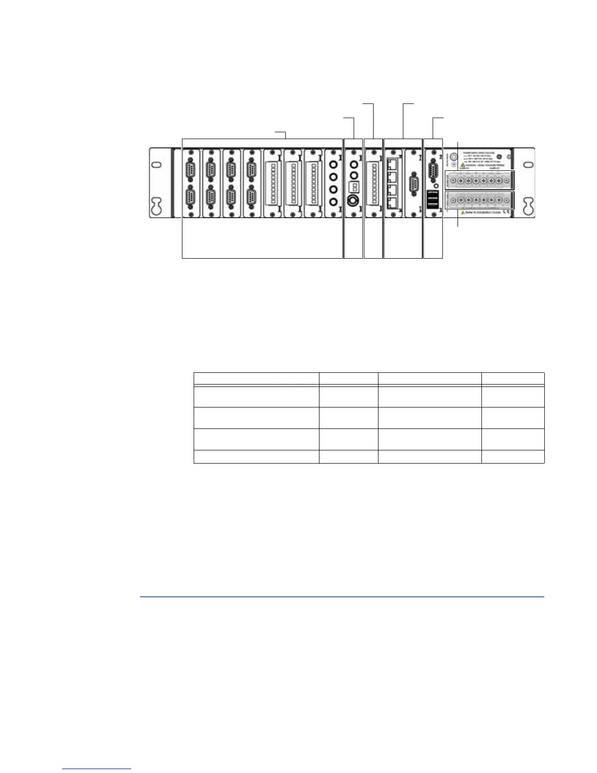
Figure 29: D400 Field and Network Connections
The types of communication cards included in your D400 depend on what was ordered for
your substation application.
For a list and detailed description of the types of communication cards available, see
Chapter 3, Setting Up Communication Cards.
General cabling requirements
Cabling required to make physical connections to the D400 are as follows:
High-voltage installations
To provide higher EMC immunity and maintain CE Mark compliance, the serial cables used
for permanent RS-232 and RS-485 connections must comply with the following
requirements:
• Cables must be shielded
• D-type connector covers must provide EMC shielding (e.g. metallized plastic or die cast
metal covers).
RS-232 connections
The D400 accepts connections to RS-232 type devices through the RS-232 Adapter. The
RS-232 Adapter (GE Item No. 520-0207LF) is an RS-232 serial I/O adapter card that plugs
into any serial communication slot (slots 1 through 8) on the D400. It contains two
independently isolated RS-232 serial ports (Port 1 and Port 2) each with a DB-9 connector.
Slot 1
Slot 2
Slot 3
Slot 4
Slot 5
Slot 6
Slot 7
Slot 8
Slot 9
Slot 10
Slot 11
Slot 12
Slot 13
Serial Communication Slots
IRIG-B Input Slot
IRIG-B Distribution Slot Network Slots
USB KVM Slot
Power Supply and
System Fail Alarms
External Power Source
Media Designation Cabling Connector
Fiber Optic Ethernet
10BaseFL
100BaseFX
62.5/125 µm or 50/125 µm
multi-mode fiber cable
ST Connectors
(820 to 850 nm)
Twisted Pair Ethernet 10/100BaseT UTP– Unshielded Twisted
Pair – CAT 5 or better
RJ-45
Redundant Twisted Pair Ethernet 10/100BaseT UTP– Unshielded Twisted
Pair – CAT 5 or better
RJ-45
PPP Serial Over External Modem RS-232 Standard RS-232 cable DB-9