80 GENERAL D400 SUBSTATION GATEWAY USER’S MANUAL
POWER SUPPLY ALARMS CHAPTER 5: POWERING UP THE D400
Power fail alarm
The Power Fail contact closure provides for an external indication upon loss of power. The
Power Fail alarm is also indicated by the Power LED on the front panel of the power supply
turning off.
The front panel Power indicator LED is lit when any one power supply is ON, but does not
indicate that any one power supply has failed.
The back panel contact closure indicator or audible alarm can be wired to operate as
follows:
• Lit when a power failure has occurred
• Lit when power is present
The Power Fail contact closure provides three contacts (terminals 1, 2 and 3) on terminal
block TB2.
Contact closure rated for 0.1 A @ 300 V maximum.
To connect the Power
Fail contact closure
1. Remove the terminal block protective plastic cover.
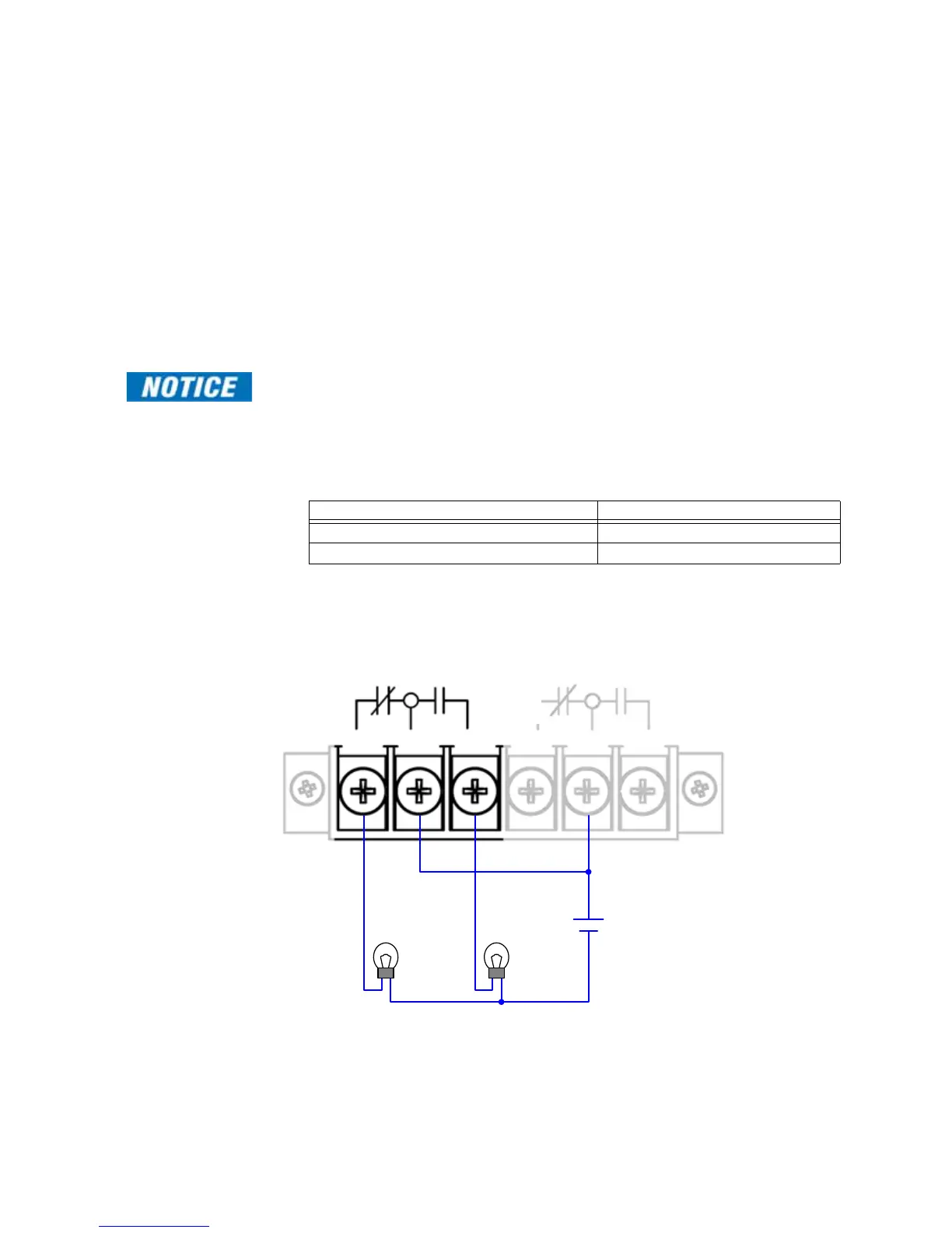
2. Wire a lamp or audible alarm to terminals 1, 2 or 3 on terminal block TB2 as follows
(see Figure 49):
For proper connection, the recommended tool torque settings for power terminal
screws are 10.8 in-lb [1.22 Nm]. A Phillips (#1) screwdriver tip is recommended.
3. Replace the terminal block protective plastic cover.
Figure 49: Power Fail Alarm Connection
To enable the indicator when power is… Wire the lamp between…
Absent Terminals 1 and 2
Present Terminals 2 and 3
Station Battery / Power Source
Light ON
after failure
Light ON
when operational
Power
Fail
System
Fail
TB2