42 GENERAL D400 SUBSTATION GATEWAY USER’S MANUAL
IRIG-B INPUT ADAPTER CHAPTER 3: SETTING UP COMMUNICATION CARDS
IRIG-B input adapter
The IRIG-B Input Adapter (GE Item No. 520-0211LF) plugs into a dedicated IRIG-B slot (slot
9) on the D400. The IRIG-B Input card accepts an IRIG-B signal in one of three input formats
through a corresponding connector type:
• Modulated IRIG-B through a BNC connector J2
AM modulated input accepts B12X, however, the SBS (straight binary seconds) in B120,
B124, and B127 are decoded but not used to set the time
• Pulse Width Code IRIG-B (TTL) through a terminal block TB1
(TTL) input accepts B00X and B237, however, the SBS field is decoded but not used to
set the time. The connector used is a 2 position pluggable terminal block, Molex P/N
39530-0002 (GE Part No. 640-0956)
• Fiber Optic through a Receive (RX) 820 to 850 nm ST connector U12
The IRIG-B signal (TTL) can be subsequently distributed to attached devices through one of
the following options:
• IRIG-B Distribution Adapter (GE Item No. 520-0212LF). See “IRIG-B distribution adapter”
on page 44.
• RS-232 Adapter (GE Item No. 520-0207LF). See “IRIG-B input adapter” on page 42.
See “IRIG-B connections” on page 58 for wiring instructions.
Configuration options
The input signal formats and output options are selectable via two switches on the IRIG-B
Input card:
• IRIG-B state option is configured by switch SW1
• Input signal format is configured by switch SW2
Follow instructions for setting the switches to select the appropriate IRIG-B signal formats
and functions
.
Factory default
The factory default setting is the Standard state on each channel.
Switch SW1 configuration
Switch SW1 controls the state option for the IRIG-B Input card. It contains two switch
positions that can be set to ON or OFF to select the appropriate IRIG-B state option.
Table 8: IRIG-B Input Card Switch SW1 Settings
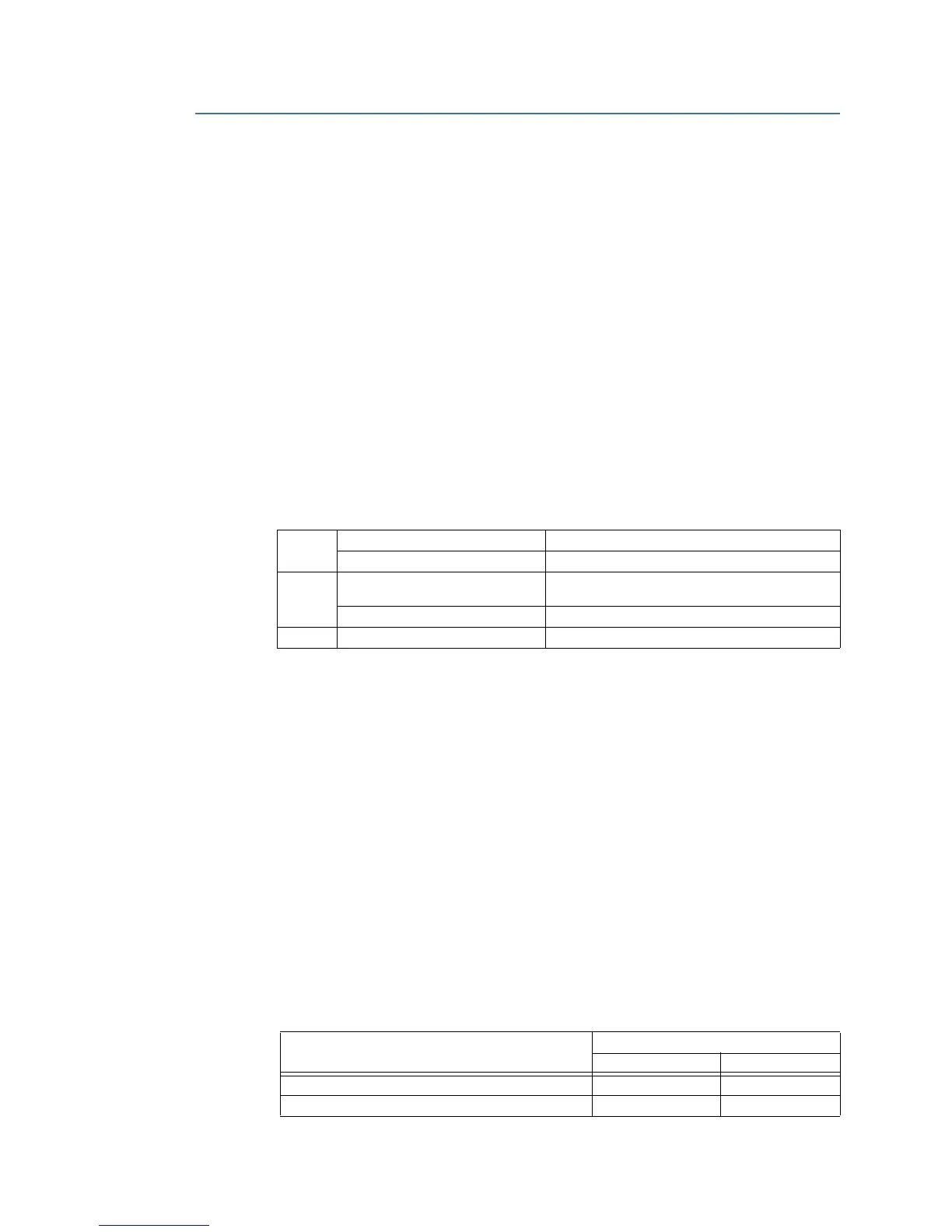
J2 Input Range 4.0 V
P-P
to 8.0 V
P-P
; No DC offset
Input Impedance >1 MΩ @ 1 kHz
TB1 Voltage Range High: > 3.5 V
Low: < 1.5 V
Load One HCMOS load
U12 Receiver Sensitivity −25.4 dBm
IRIG-B State Option SW1 Switch Positions
12
Standard (default) ON OFF
Fiber TX Continuous Test Mode OFF ON