CHAPTER 8: SERVICING THE D400 DUAL ETHERNET UPGRADE KIT WITH CARD 580-2717
D400 SUBSTATION GATEWAY USER’S MANUAL GENERAL 103
Perform this procedure on an ESD-safe surface to prevent damage to the D400 device and
its components.
Installing the 580-2717 dual ethernet card
To install the Dual Ethernet Upgrade Kit:
1. Power down your D400 device.
2. Remove the D400 main module from the chassis. See “Removing the D400 main
module” on page 99.
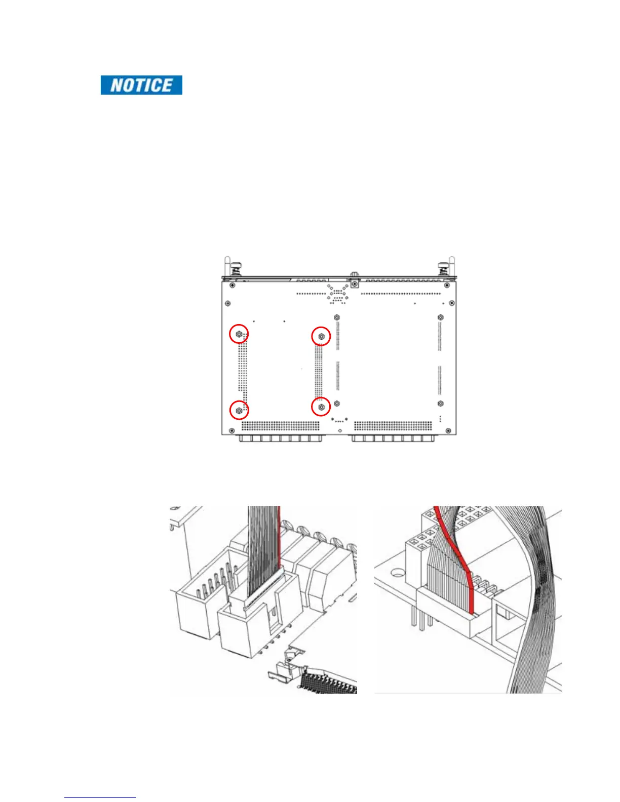
3. Locate the four mounting holes in the D400 main module PCB board noted below.
Attach the hexagonal standoffs to the top of the main board and secure the standoffs
using the four provided hexagonal nuts.
Figure 54: Dual Ethernet upgrade kit - four mounting holes
4. Plug the provided cable assembly into connector P3 on the D400 main module. Plug
the other end of this cable into connector J5 on the Ethernet Module card.
Figure 55: Dual Ethernet upgrade kit with card 580-2717 - cable connection
Connector P3 – red wire closest to face of unit Connector J5 – red wire closest to Ethernet port