CHAPTER 3: SETTING UP COMMUNICATION CARDS RS-232 ADAPTER
D400 SUBSTATION GATEWAY USER’S MANUAL GENERAL 35
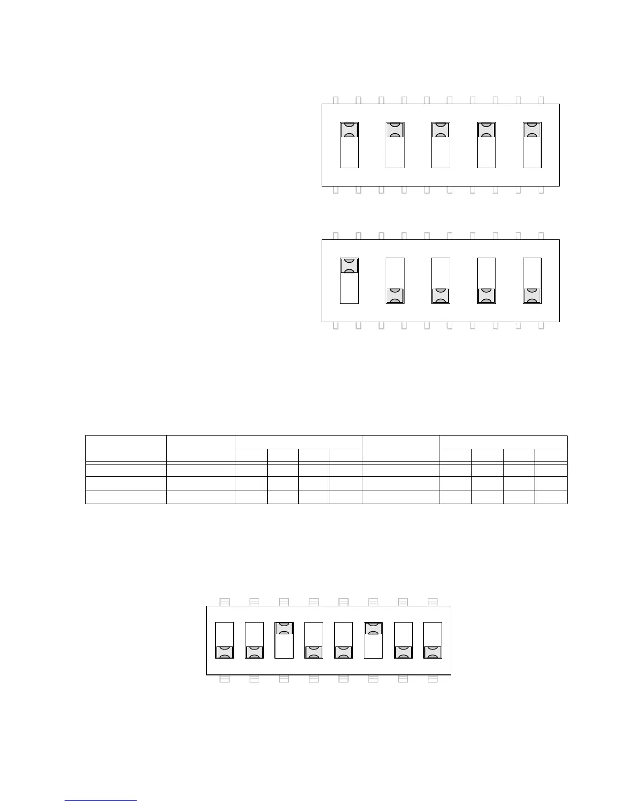
Figure 9: Switch SW1/SW2 configuration for port DTE (default)
Figure 10: Switch SW1/SW2 configuration for port DCE
Switch SW3/SW4 configuration
Switches SW3 (for Port 2) and SW4 (for Port 1) control the signals on Pins 4 and 6 of the RS-
232 port. Each switch contains four switch positions that can each be set to ON or OFF to
select the appropriate function for the port option.
Table 5: RS-232 Card Switch SW3/SW4 Settings
The switch positions are listed for:
• DTE (Pin 4 DTR Output to DCE and Pin 6 DSR Input from DCE). See Figure 11.
• DCE (Pin 4 DTR Input from DTE and Pin 6 DSR Output to DTE). See Figure 12.
• IRIG-B Enable (on Pin 4) and Ground (on Pin 6). See Figure 13.
Figure 11: Switch SW3/SW4 configuration for port DTE (default)
Function Pin 6 Signal SW3/SW4 Positions Pin 4 Signal SW3/SW4 Positions
1234 5678
DTE (default) DSR Input OFF OFF ON OFF DTR Output OFF ON OFF OFF
DCE DTR Output OFF ON OFF OFF DSR Input OFF OFF ON OFF
IRIG-B Enable Ground OFF OFF OFF ON IRIG-B Output ON OFF OFF OFF