34 GENERAL D400 SUBSTATION GATEWAY USER’S MANUAL
RS-232 ADAPTER CHAPTER 3: SETTING UP COMMUNICATION CARDS
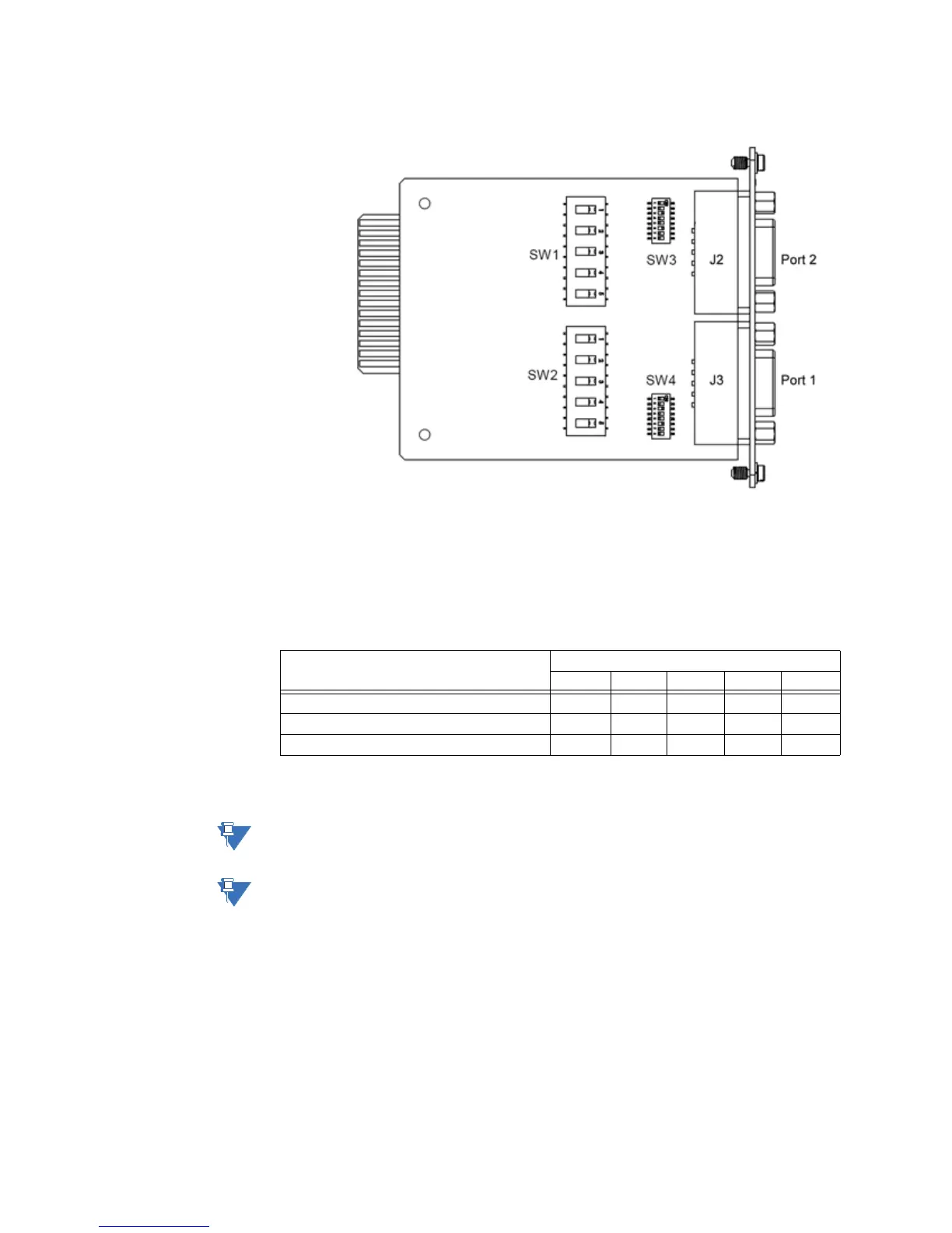
Figure 8: RS-232 adapter top side
Switch SW1/SW2 configuration
Switches SW1 (for Port 2) and SW2 (for Port 1) control the signal type of the RS-232 port.
Each switch contains five switch positions that can each be set to position A or B to select
the appropriate port option.
Table 4: RS-232 Card Switch SW1/SW2 Settings
*Use DTE or DCE settings as appropriate
DCD output is not supported in DCE mode.
Each +5 V output is independently isolated and fused with a PTC (positive temperature
coefficient) resettable fuse at 320 mA at 65 °C.
Port Option SW1/SW2 Switch Position
12345
DTE (default) - see Figure 9 A A A A A
DCE - see Figure 10 — B B B B
+5 V (320 mA) isolated source B * * * *