60 GENERAL D400 SUBSTATION GATEWAY USER’S MANUAL
HOT STANDBY FIBER OPTIC CONNECTIONS CHAPTER 4: CONNECTING TO DEVICES AND NETWORKS
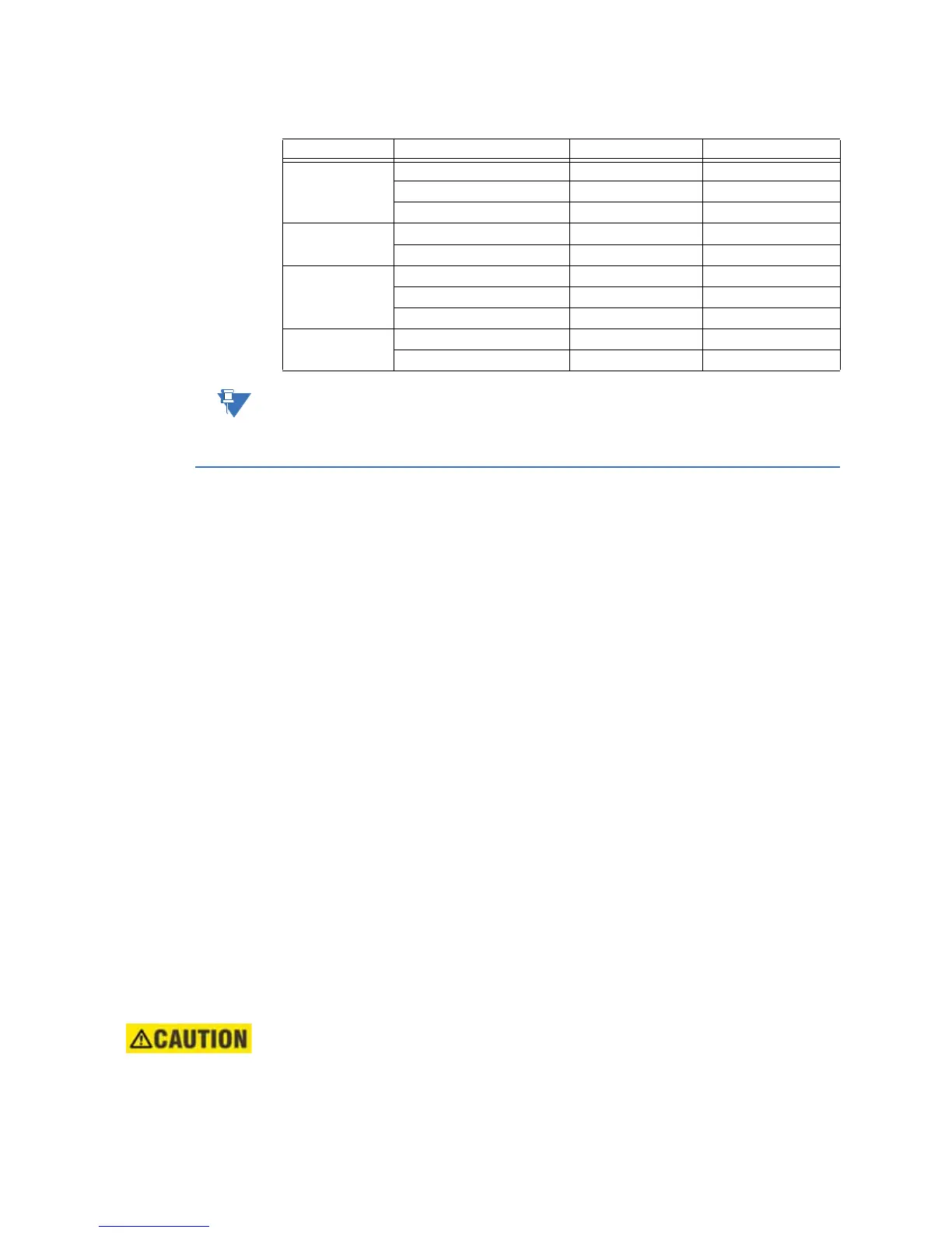
Table 13: IRIG-B Distribution Terminal Block Signal Definitions
The terminal block positions are numbered from 1 to 10 starting from the bottom of the
card.
Hot standby fiber optic connections
The Hot Standby Fiber Optic Ethernet Switches support single-IP redundancy for the D400.
They provide automated fail over between two Ethernet fiber optic network connections
(RX1/TX1 and RX2/TX2) that share a single MAC address. The 10-BaseFL switch (GE Item
No. 520-0214LF) operates at 820-850 nm and the 100BaseFX switch (GE Item No. 520-
0215LF) operates at 1300 nm.
Hot Standby Fiber Optic Ethernet Switches can be installed in the NET1 or NET2 slot (slots
11 and 12) on the D400.
If two Hot Standby Ethernet switches are installed in the NET slots, the system may be used
in a dual-IP redundancy mode. That is, each switch can be configured with a different IP
address to provide a back up network connection if the primary channel fails.
You can use the following glass optical fiber (GOF) cabling with the D400 Hot Standby Fiber
Optic Ethernet Switches:
• 50/125 µm core/cladding multi-mode (gradient index) cable
• 62.5/125 µm core cladding multi-mode (gradient index) cable
• 100/140 µm core/cladding multi-mode (gradient index) cable
• 200 µm core Hard-Clad Silica (HCS) multi-mode (step index) cable
You can use the following fiber optic terminations for D400 cabling:
• ST Connectors
When calculating cable length, consider the following optical power levels:
• 100BaseFX optical transmitter power is –15.0 ± 4 dBm
• 100BaseFX optical fiber receiver sensitivity is typically –34.0 dBm
• 10BaseFL optical transmitter power is –19.0 ± 2 dBm
• 10BaseFL optical fiber receiver sensitivity is typically –31.0 dBm
LED transmitters are classified as IEC 60825-1 Accessible Emission Limit (AEL) Class
1M. Class 1M devices are considered eye safe to the unaided eye. Do not view directly
with optical instruments.
Channel Terminal Block Position Function Signal Flow
Channel 1 1 IRIG-B TTL OUT
2 GND -
3 FGND -
Channel 2 4 IRIG-B TTL OUT
5 GND -
Channel 3 6 IRIG-B TTL OUT
7 GND -
8 FGND -
Channel 4 9 IRIG-B TTL OUT
10 GND -