CHAPTER 2: INSTALLING THE D400 PHYSICAL INSTALLATION
D400 SUBSTATION GATEWAY USER’S MANUAL GENERAL 29
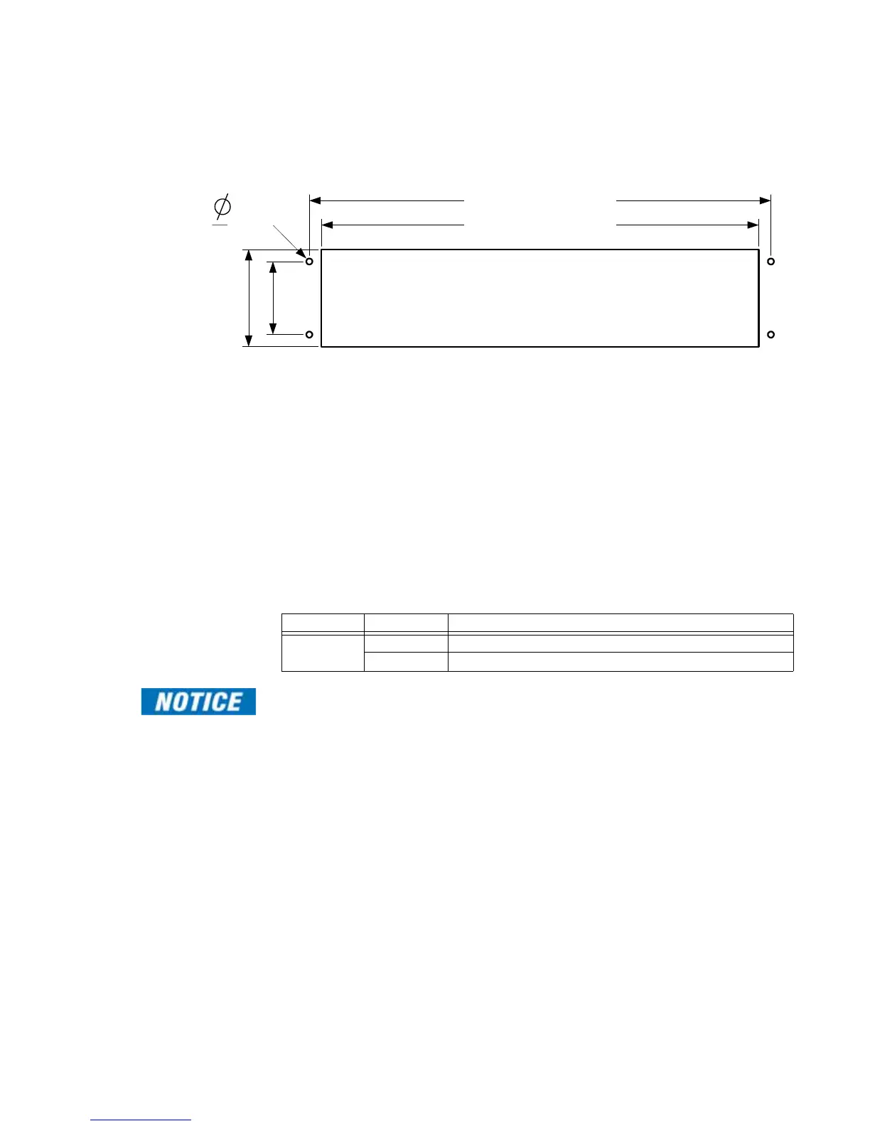
Panel mount
If you are using a panel cutout, use the following cutout dimensions:
Figure 6: D400 front panel dimensions
Battery installation
To insert the Lithium
battery
Remove the D400 main module from the chassis and insert the battery in the battery
holder BT1. See
“Replacing the battery” on page 100 for more information.
Battery removal
J12 - battery backup
enable/disable
The D400 card contains a 3.6V lithium battery to maintain NVRAM contents (processor and
date/time) in the event of a power failure. Move jumper J12 to position 2-3 when storing
board for extended periods. Return jumper J12 to position 1-2 for normal operation.
Table 3 describes the J12 jumper positions and associated functions.
Table 3: Jumper J12 positions
Disconnect the battery if the board is to be stored for extended periods. The conserves the
battery energy.
1.75 in.
[44.46 mm]
3.50 in.
[88.90 mm]
Cutout for panel mounting
18.3 in. [464.8 mm]
17.5 in. [444.5 mm]
.162 in.
[4.1 mm]
Jumper Position Function
J12 pin 1 to 2 Connects the battery to the NVRAM and date/time
pin 2 to 3 Disconnects the battery from the NVRAM and date/time