62 GENERAL D400 SUBSTATION GATEWAY USER’S MANUAL
NETWORK CONNECTIONS CHAPTER 4: CONNECTING TO DEVICES AND NETWORKS
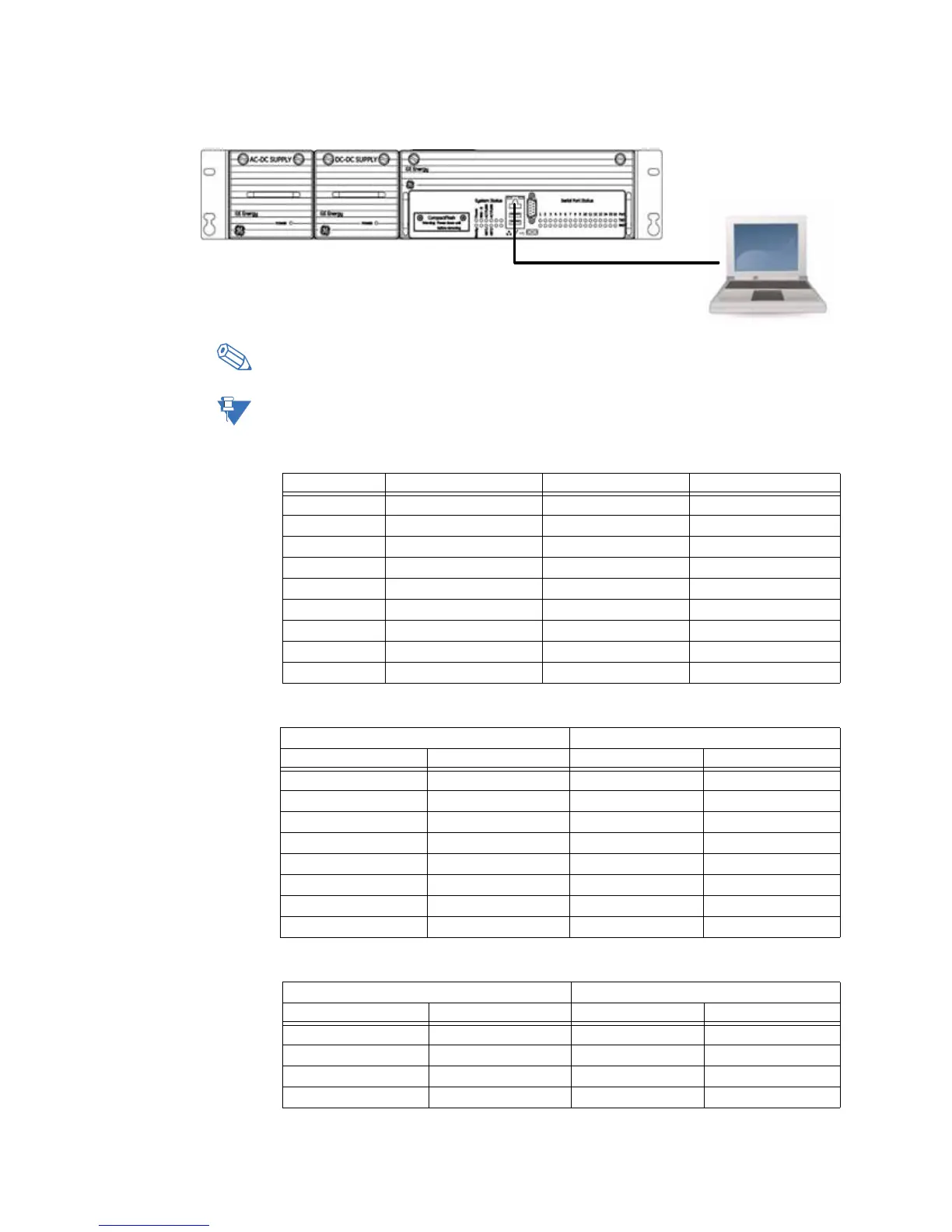
Figure 38: Front network port
If your portable PC contains an older Ethernet chip and you are having difficulty
connecting, try forcing the connection speed to 10 Mbps, full duplex, on your PC.
The network interface must be configured before the network ports can be used. See
“Connecting to the D400 for the first time” on page 83 for more information.
Table 15: Ethernet RJ-45 Connector Signal Definitions
Table 16: Ethernet Crossover Cable (RJ-45) Pin Out
Table 17: Ethernet Straight-Through Cable (RJ-45) Pin Out
Position Function Signal Flow Color
1 RX+ IN White w/ Orange
2 RX− IN Orange
3 TX+ OUT White w/ Green
4 P1+ - Blue
5 P1− - White w/ Blue
6 TX− OUT Green
7 P2+ - White w/ Brown
8 P2− - Brown
Shield - -
D400 Switch/Hub
Name Pin Pin Name
TX_D1+ 1 3 RX_D2+
TX_D1− 2 6 RX_D2−
RX_D2+ 3 1 TX_D1+
RX_D2− 4 2 TX_D1−
BI_D3+ 5 7 BI_D4+
BI_D3− 6 8 BI_D4−
BI_D4+ 7 4 BI_D3+
BI_D4− 8 5 BI_D3−
D400 PC
Name Pin Pin Name
TX_D1+ 1 1 RX_D2+
TX_D1− 2 2 RX_D2−
RX_D2+ 3 3 TX_D1+
RX_D2− 4 4 TX_D1−