78 GENERAL D400 SUBSTATION GATEWAY USER’S MANUAL
POWER CONNECTIONS CHAPTER 5: POWERING UP THE D400
To connect the power
source to the D400
1. Remove the terminal block TB1 protective plastic cover.
2. Connect power source as follows:
For proper connection, the recommended tool torque settings for power terminal
screws are 10.8 in-lb [1.22 Nm]. A Phillips (#1) screwdriver tip is recommended.
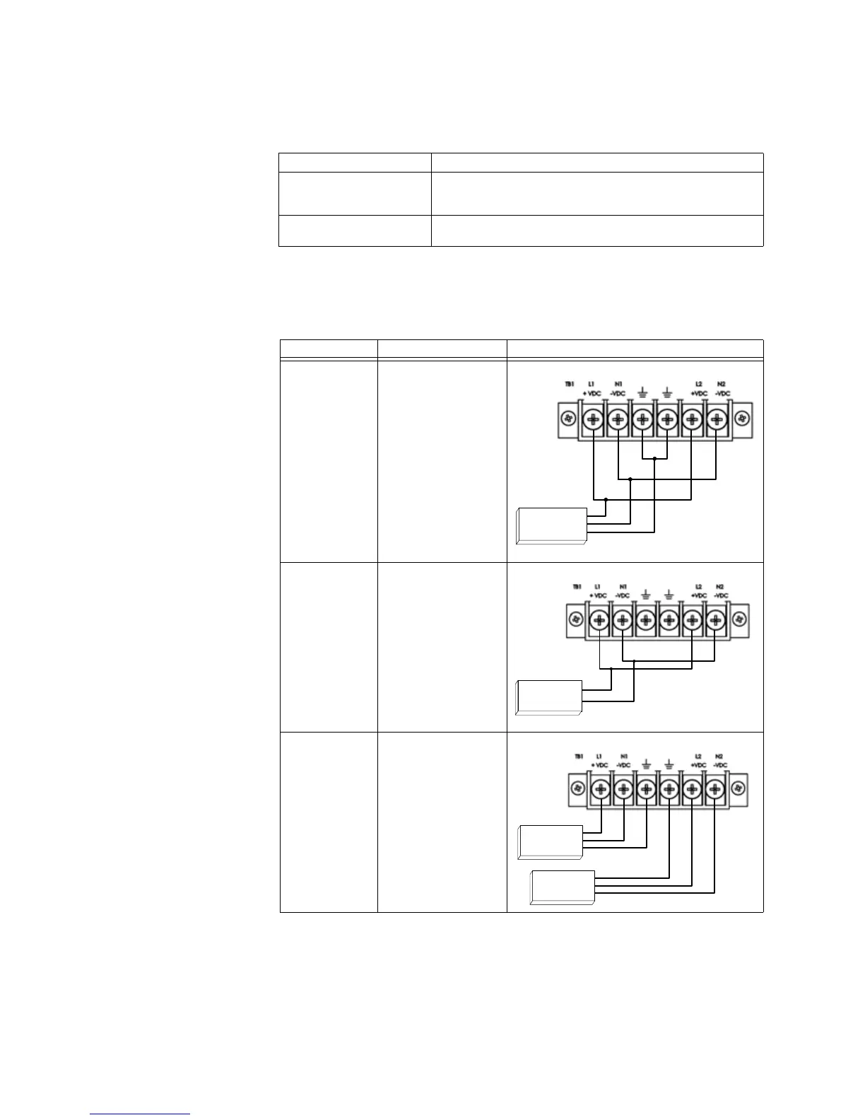
See the wiring diagrams in Table 22.
Table 22: Power Source Configurations
If your power supply is… then…
AC Connect the AC line connection to the L connection point(s) and
the AC neutral connection to the
N connection point(s) on
terminal block
TB1
DC Connect the DC power supply, observing the correct polarity, to
the
+VDC and −VDC connection point(s) on terminal block TB1
Power Source Connection Wiring Diagram
Single External AC
Power Source
Connected to SUPPLY1
and
SUPPLY2 input
terminals.
Single External DC
Power Source
Connected to SUPPLY1
and
SUPPLY2 input
terminals.
Two External AC
Power Sources
with Optional
Redundant D400
AC/DC Power
Supply
First source connected
to
SUPPLY1 terminals.
Second source
connected to
SUPPLY2
terminals.
L
N
GND
AC Power Source
Supply 1 Supply 2
DC Power Source
+
-
Supply 1
Supply 2
AC Power Source #1
L
N
GND
L
N
GND
AC Power Source #2
Supply 1 Supply 2