2-4 Dash™ 3000/4000/5000 2000966-386D
Equipment Overview
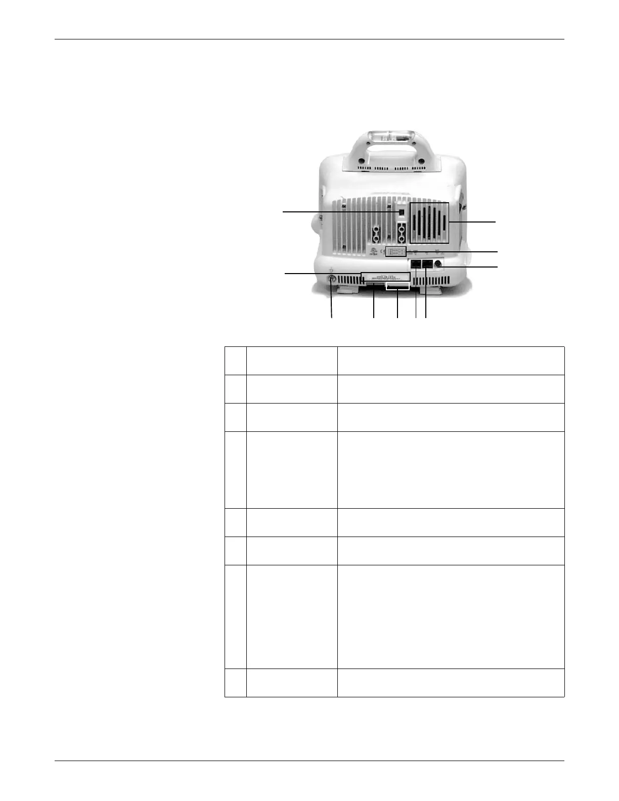
Back
1 Line voltage selector Matches the line voltage and frequency rating for your
country.
2 Product code label Identifies the product code for this monitor for identification
and service needs.
3 Equipotential stud Provides a common reference to an auxiliary device via a
ground wire attached to the stud.
4 DC power connector Provides connection for DC power cable. The internal power
supply converts the AC current to DC power.
The monitor is preset at the factory for a specific AC voltage.
Refer to the label on the back of the unit for the voltage and
current requirements. Before applying power, verify the
power requirements match your power supply.
5 Wireless transmitter
label
Identifies monitors that contain an internal wireless
transmitter for network communication.
6 Ethernet connector Provides network connections to other monitors and devices
used in the patient monitoring network.
7 Aux connector Provides serial connection to compatible auxiliary devices,
including:
Remote control
TRAM-RAC housing
Remote display
Nellcor
®
395 pulse oximeter
Aspect
®
BISx module
8 Defib Sync
connector
Provides analog output signals to other equipment. For
more information, refer to Analog Output on page 8-6.