EasyManuals Logo

GE LOGIQ E9 Service Manual

GE LOGIQ E9
808 pages
To Next Page IconTo Next Page
To Previous Page IconTo Previous Page
Page #413 background imageLoading...
Page #413 background image
GE
D
IRECTION 5535208-100, REV. 2 LOGIQ E9 SERVICE MANUAL
Chapter 8 Replacement procedures 8 - 67
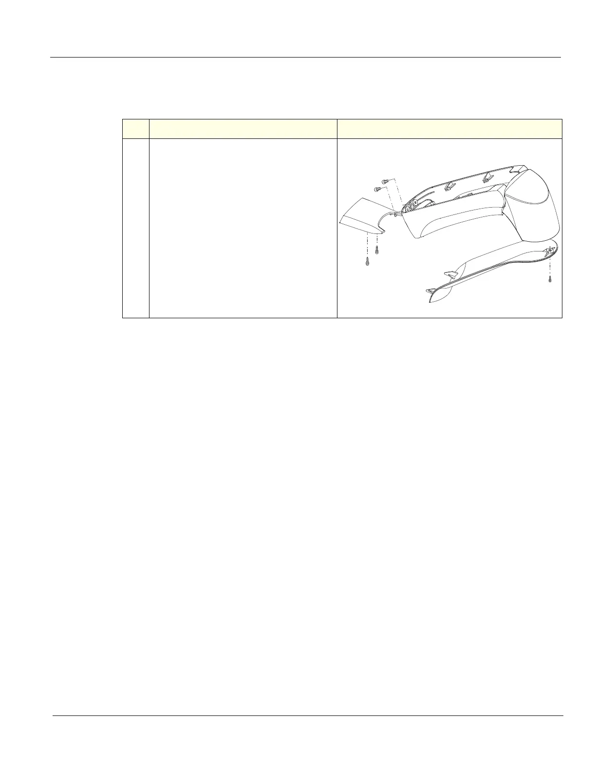
8-5-15 LCD Monitor V2 Arm Assembly Covers replacement (cont’d)
Table 8-45 LCD Monitor V2 Arm Assembly Covers removal and installation - R5.x and later
Steps Corresponding Graphic
1.
Pan Arm Down Cover (1), remove two
Phillips screws and lift the cover off.
Lift Arm Cover - Right (2) and Lift Arm
Cover - Left (3), remove the 3 mm screws
and slide the Cover toward the Monitor.
Joint Cover (4), slightly push the bottom of
the Cover forward to “bow“ the cover and
pry at the leading, forward edge of the
Cover to remove.
Extension Arm Cover (5), remove the
3 mm screw and lower cover.
Install covers in the reverse motion. To
install the Joint Cover, place top of Cover
into position and snap into place.
1
3
2
4
5

Table of Contents

Other manuals for GE LOGIQ E9

Questions and Answers:

Question and Answer IconNeed help?

Do you have a question about the GE LOGIQ E9 and is the answer not in the manual?

GE LOGIQ E9 Specifications

General IconGeneral
TypeUltrasound System
3D/4D ImagingYes
Transducer Ports4 active ports
ConnectivityDICOM, USB, Ethernet
ApplicationsAbdominal, Vascular, Musculoskeletal, Small Parts, Urology, Pediatric, Cardiac, Obstetrics/Gynecology
TransducersLinear, Convex, Phased Array, Volume
Doppler ModesColor Doppler, Power Doppler, Pulsed Wave Doppler, Continuous Wave Doppler
ElastographyYes
Advanced FeaturesB-Flow, Volume Navigation
PortabilityCart-based system
Display19-inch high-resolution LCD monitor

Related product manuals