EasyManuals Logo

GE LOGIQ E9 Service Manual

GE LOGIQ E9
808 pages
To Next Page IconTo Next Page
To Previous Page IconTo Previous Page
Page #450 background imageLoading...
Page #450 background image
GE
D
IRECTION 5535208-100, REV. 2 LOGIQ E9 SERVICE MANUAL
8 - 104 Section 8-6 - Replacing Top Console Parts
8-6-3-1 LCD Arm replacement - R3.x and earlier (cont’d)
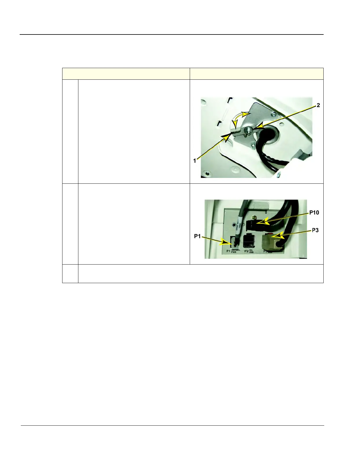
Table 8-66 LCD Arm assembly installation
Steps Corresponding Graphic
1. Carefully install the LCD Arm assembly into
position, first feeding the LCD Arm cables
down through the console opening.
Push the LCD Mount Lock handle (1) into
locked the position (shown LOCKED).
DO NOT adjust nut (2).
LCD Mount Lock Handle
2. Connect the LCD cables; video (P10) and
power (P3) from the connectors on the
Bulkhead. The Gel Warmer cable (P1)
does not have to be removed.
Install the Bulkhead Cover.
Install the LCD Monitor assembly.
LCD Cables at Bulkhead
3.
Perform Functional Checks. See: 8-6-3-4 - Calibration and adjustments, 8-6-3-5 - Verification
and 8-6-3-6 "Functional Checks" on page 8-117.

Table of Contents

Other manuals for GE LOGIQ E9

Questions and Answers:

Question and Answer IconNeed help?

Do you have a question about the GE LOGIQ E9 and is the answer not in the manual?

GE LOGIQ E9 Specifications

General IconGeneral
TypeUltrasound System
3D/4D ImagingYes
Transducer Ports4 active ports
ConnectivityDICOM, USB, Ethernet
ApplicationsAbdominal, Vascular, Musculoskeletal, Small Parts, Urology, Pediatric, Cardiac, Obstetrics/Gynecology
TransducersLinear, Convex, Phased Array, Volume
Doppler ModesColor Doppler, Power Doppler, Pulsed Wave Doppler, Continuous Wave Doppler
ElastographyYes
Advanced FeaturesB-Flow, Volume Navigation
PortabilityCart-based system
Display19-inch high-resolution LCD monitor

Related product manuals