GE
D
IRECTION 5535208-100, REV. 2 LOGIQ E9 SERVICE MANUAL
Chapter 8 Replacement procedures 8 - 109
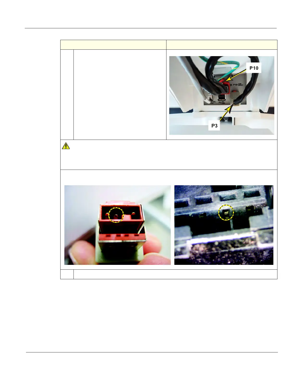
4.
Connect the LCD cables; video (P10) and
power (P3) from the LCD.
The Video Cable has a retainer and screw.
Tighten the screw with a small, flat blade
screwdriver.
Make sure the cables do not interfere with
the installation of the cables. It may be
necessary to push the cables up before
installing the Bulkhead Cover.
DO NOT connect the LCD power cable to the power (P3) connector on the Bulkhead when the
LOGIQ E9 is powered up. Damage to the LCD Power Cable and/or the Bulkhead Board can
occur. See images below of damage that can occur.
48VDC pin in the P3 connector (center pin), shows damage.
The outside two pins are Ground. Cable left, Bulkhead Connector right.
5.
Re-install the LCD Monitor.
Table 8-68 LCD Monitor V2 Arm assembly installation - R4
Steps Corresponding Graphic
 Loading...


