GE
D
IRECTION 5535208-100, REV. 2 LOGIQ E9 SERVICE MANUAL
8 - 202 Section 8-9 - BEP (Back End Processor) parts replacement
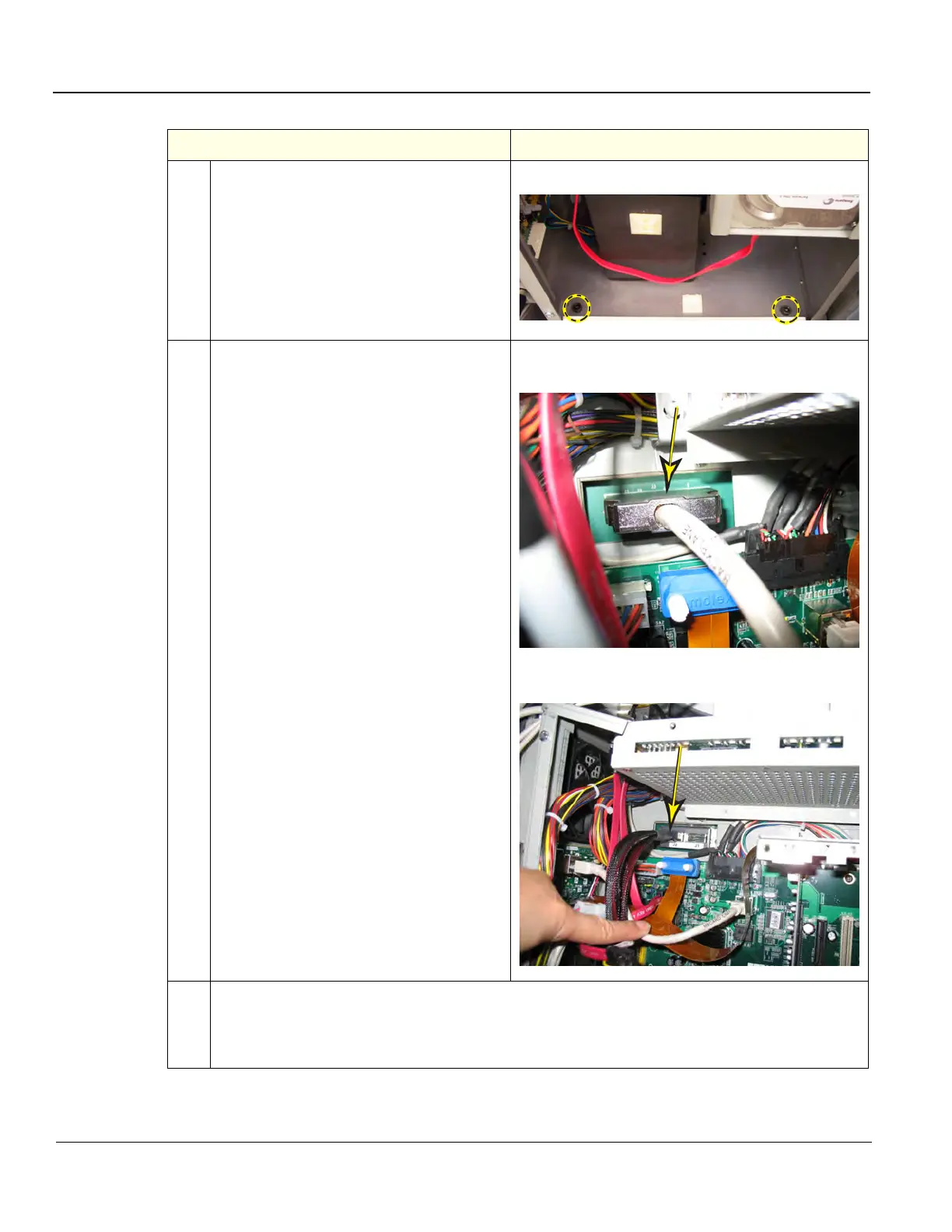
4.
Remove the two 5 mm HEX key screws at
the inside base of the BEP.
BEP Base HEX key screws
5. Reach inside the BEP to disconnect the
BEP to Backplane cable from J3 on a GFI
Configuration.
Release the lock connector for the BEP to
Backplane cable, J2 (left) on a MRX
Configuration. Keep the cable to transfer to
the replacement BEP.
BEP Cable to Backplane J3 of GFI Configuration
(views inside the BEP)
BEP Cable to Backplane, J2 (left) of
MRX Configuration
6.
Slide:
• the entire BEP away from the system approximately one inch, then finish removing the Printer
Tray.
• the entire BEP out of chassis and remove the BEP from the system.
Table 8-122 BEP removal - R3.x and earlier
Steps Corresponding Graphic