GE
D
IRECTION 5535208-100, REV. 2 LOGIQ E9 SERVICE MANUAL
Chapter 8 Replacement procedures 8 - 211
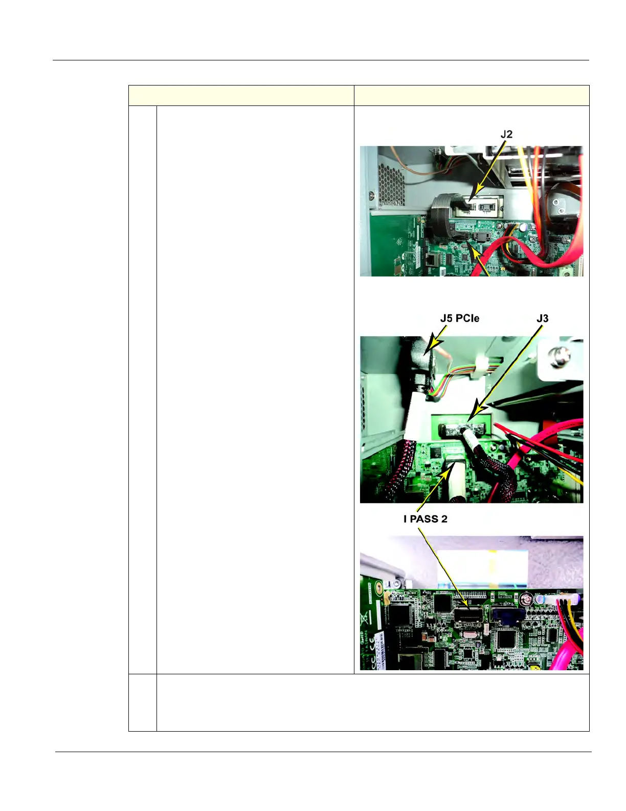
5. Release the lock connector for the BEP to
Backplane cable, J2 (left) on a MRX
Configuration.
Or, the Backplane cable, J3 (right) and J5
PCIe to the Card Rack on a GFI
Configuration, using a BEP6. Keep the
cable to transfer to the replacement BEP.
BEP Cable to Backplane, J2 - BEP6
BEP Cable to Backplane J3 of GFI Configuration
(view inside the BEP)
6.
Slide:
• the entire BEP away from the system approximately one inch, then finish removing the Printer
Tray.
• the entire BEP out of chassis and remove the BEP from the system.
Table 8-126 BEP removal - R4.x and later
Steps Corresponding Graphic