EasyManuals Logo

GE LOGIQ E9 Service Manual

GE LOGIQ E9
808 pages
To Next Page IconTo Next Page
To Previous Page IconTo Previous Page
Page #633 background imageLoading...
Page #633 background image
GE
D
IRECTION 5535208-100, REV. 2 LOGIQ E9 SERVICE MANUAL
Chapter 8 Replacement procedures 8 - 287
8-11-8-2 Printer Bracket installation
Table 8-180 Printer Bracket installation
Steps Corresponding Graphic
1.
Cut the tie wrap that secures the Drive Gear Assembly power cable to the top of the Targa.
Remove the Cable Tie Mount from the top of the Targa Frame.
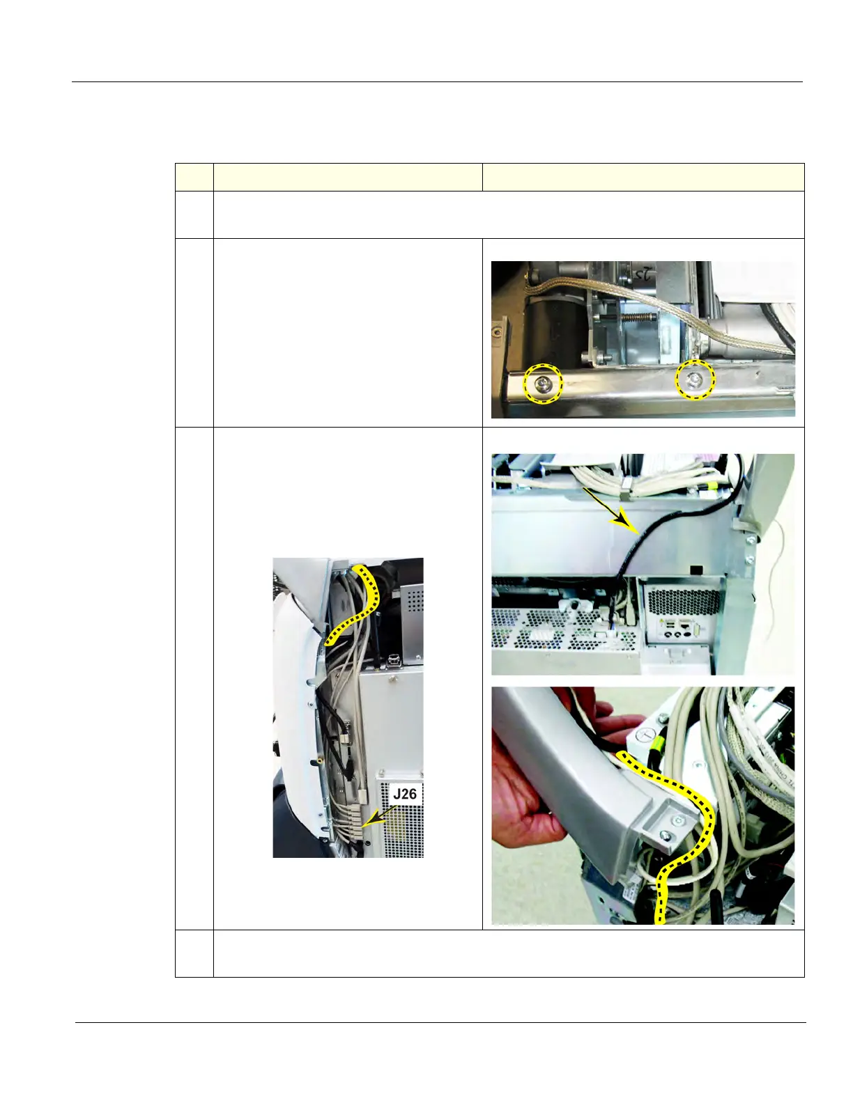
2.
Remove the two T30 torx screws that
secure the Z-Mechanism to the Targa.
3.
Route the Printer Cables as shown. Route
the Power Cable as shown and the USB
Cable on top of the Targa, along the inside
edge of the Rear Handle. Continue to route
the USB Cable inside the Targa to J26 on
the BEP.
4.
Reinstall the Rear, but DO NOT install the screws.
MAKE SURE the Printer USB and Power Cables DO NOT get pinched.

Table of Contents

Other manuals for GE LOGIQ E9

Questions and Answers:

Question and Answer IconNeed help?

Do you have a question about the GE LOGIQ E9 and is the answer not in the manual?

GE LOGIQ E9 Specifications

General IconGeneral
TypeUltrasound System
3D/4D ImagingYes
Transducer Ports4 active ports
ConnectivityDICOM, USB, Ethernet
ApplicationsAbdominal, Vascular, Musculoskeletal, Small Parts, Urology, Pediatric, Cardiac, Obstetrics/Gynecology
TransducersLinear, Convex, Phased Array, Volume
Doppler ModesColor Doppler, Power Doppler, Pulsed Wave Doppler, Continuous Wave Doppler
ElastographyYes
Advanced FeaturesB-Flow, Volume Navigation
PortabilityCart-based system
Display19-inch high-resolution LCD monitor

Related product manuals