CHAPTER 1: INTRODUCTION DESCRIPTION OF THE 850 FEEDER PROTECTION SYSTEM
850 FEEDER PROTECTION SYSTEM – INSTRUCTION MANUAL 1–3
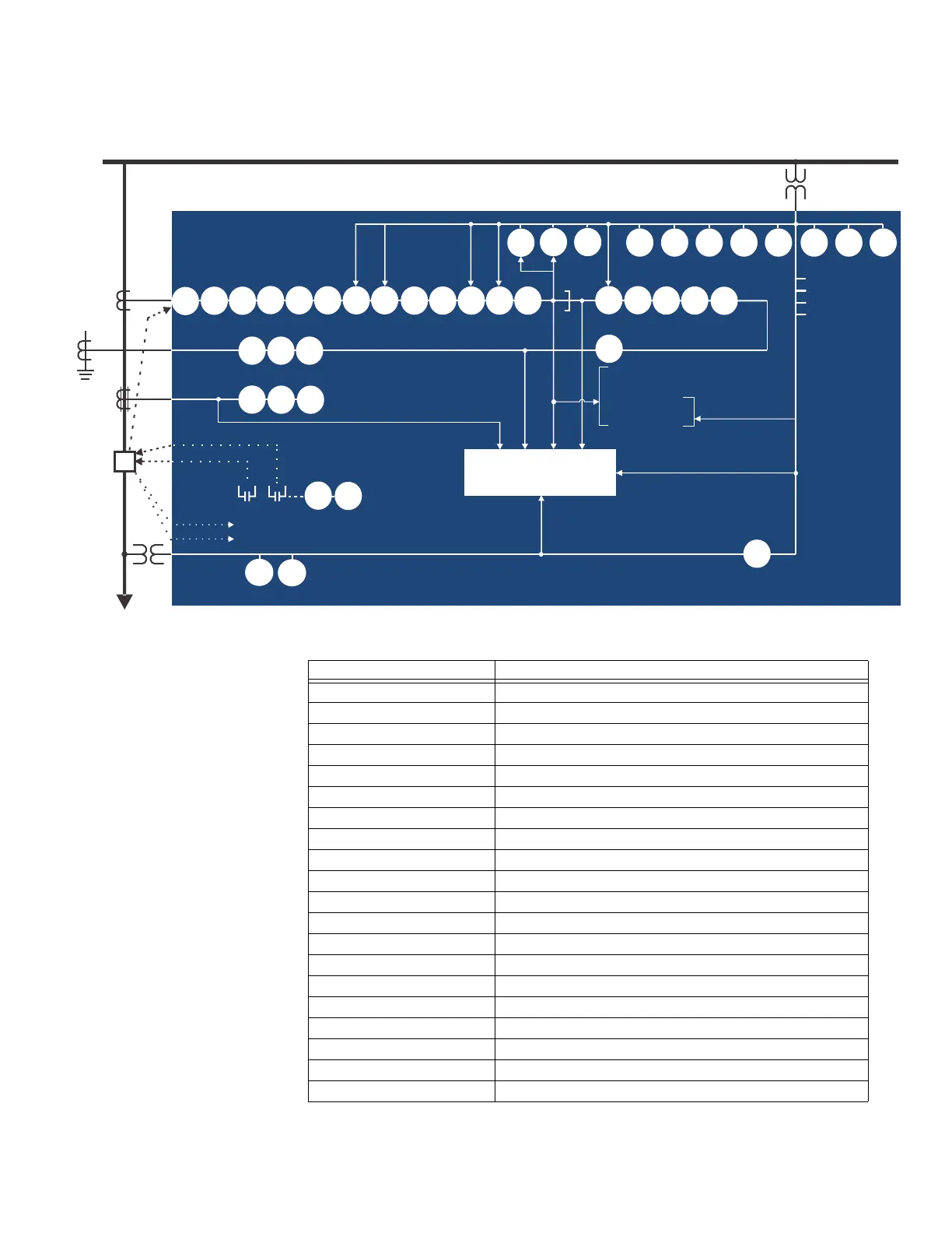
Figure 1-1: Single Line Diagram
Table 1-1: ANSI Device Numbers and Functions
892770A4.CDR
3 CTs
CT
27P
59P
59N
59_2
VTFF
81U
81O
81R
51N 50N 67N
87G
27X
59X
METERING
TRANSIENT RECORDER
EVENT RECORDER
FAULT REPORT
LOAD
BUS
TRIP
52
CLOSE
MONITORING
CLP50BF 51P 50P 67P 51_2 50_2 67_2 49
50G/
51G
51G
50G
67G
50G/
51G
51SG
50SG 67SG
25
32N
V_2
BUS
BREAKER
32
850 Feeder Protection System
V_0
POLE DISCORDANCE*
SOTF*
Fast Underfrequency
UV Restoration
UF Restoration
Bus Transfer
MCB
LIGHT
Broken Conductor
Load Encroachment
CT Supervision
Demand
Pulsed Outputs
Harmonic Detection
37*
21YN 27Q 27T
79
AFP
* 850-D only
55
ANSI Device Description
21 YN Neutral Admittance
25 Synchrocheck
27P Phase Undervoltage
27Q UV Reactive Power
27T Timed Undervoltage Protection
27X Auxiliary Undervoltage
32 Directional Power
32N Wattmetric Ground Fault (Wattmetric zero sequence directional)
37 Undercurrent
49 Thermal Overload
50BF Breaker Failure
50G Ground Instantaneous Overcurrent
50SG Sensitive Ground Instantaneous Overcurrent
50N Neutral Instantaneous Overcurrent
50P Phase Instantaneous Overcurrent
50_2 Negative Sequence Instantaneous Overcurrent
51G Ground Time Overcurrent
51SG Sensitive Ground Time Overcurrent
51N Neutral Time Overcurrent
51P Phase Time Overcurrent