CHAPTER 4: SETPOINTS MONITORING
850 FEEDER PROTECTION SYSTEM – INSTRUCTION MANUAL 4–253
Monitoring
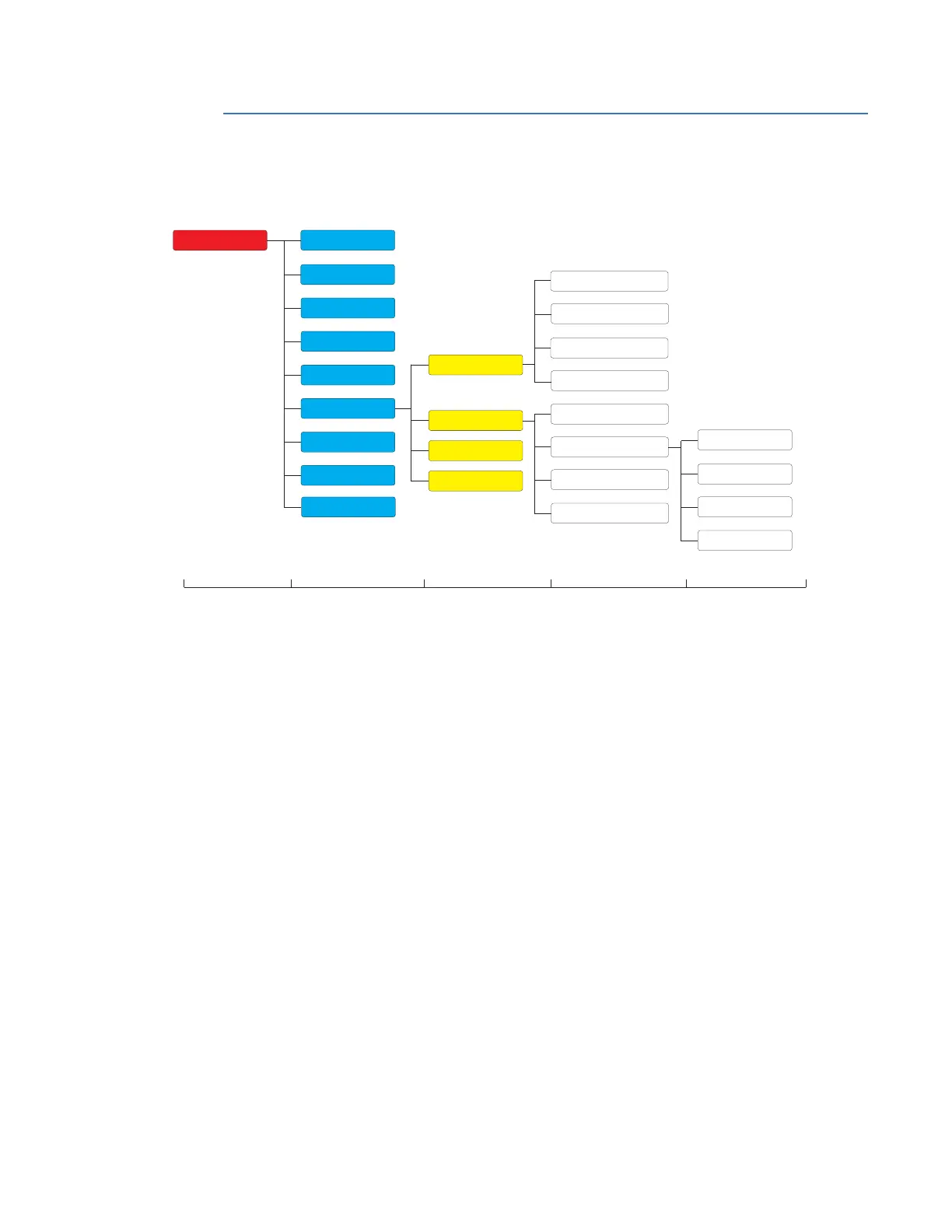
Figure 4-105: Monitoring Display Hierarchy
Trip and Close Circuit Monitoring
The 850 relay provides Trip and Close Circuit Monitoring elements.
The first and second Form A relay outputs on slot “F” include a circuit to monitor the DC
voltage across the output contact when it is open. To do that, an external jumper is wired
between the terminals “FA_1 COM” and “FA_1 OPT/V” for the Trip coil monitoring, or/and
“FA_2 COM” and “FA_2 OPT/V” for the Close coil monitoring.
The monitor contains a level detector whose output is set to logic 1 (ON) when the voltage
is above 20 volts. The voltage monitor is used to check the health of the overall trip and
closing circuit.
The two figures below show the two different connections of the breaker trip and close
coils to the relay’s trip and close output relays for either no voltage monitoring and for
voltage monitoring of the circuits.
Level 1 Level 2 Level 3 Level 4
Setpoints
Device
System
Inputs
Outputs
Protection
Monitoring
Control
FlexLogic
Data Capture
Functions
Breaker
Power Factor
Demand
Digital Counters
Pulsed Outputs
Trip Circuit Monitoring
Close Circuit Monitoring
Breaker Arcing Current
Breaker Health
Apparent Power
Level 5
Reactive Power
Real Power
Current
Testing
Data Capture
RTD Temperature
e
Loss of Comms