CHAPTER 4: SETPOINTS PROTECTION
850 FEEDER PROTECTION SYSTEM – INSTRUCTION MANUAL 4–239
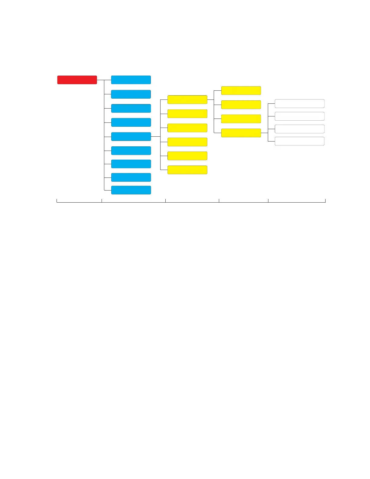
Frequency Elements
Figure 4-100: Frequency Elements Display Hierarchy
Underfrequency (81U) The 850 can be used as the primary detecting relay in automatic load-shedding schemes
based on underfrequency. The need for such a relay arises if during a system disturbance,
an area becomes electrically isolated from the main system and suffers a generation
deficiency due to the loss of either transmission or generation facilities. If reserve
generation is not available in the area, conditions of low system frequency occur which
can lead to a complete collapse. The 850
relay provides six identical Underfrequency
(UNDERFREQ) elements per protection group, or a total of 36 elements, which can
automatically disconnect sufficient load to restore an acceptable balance between load
and generation. The Underfrequency element can be set as an instantaneous element
with no time delay or as a definite time delayed element. The Underfrequency element
has the programmable minimum operating thresholds to prevent undesired operation
during periods of light load or unavailable voltage. The input voltages are the three phase-
to-phase voltages from delta connected VTs (PTs), three phase-to-ground voltages from
wye connected VTs (PTs), or single phase auxiliary voltage. The input currents are the three
phase currents.
The Underfrequency Pickup flag is asserted when the measured frequency of the specified
source is below the PKP value and the voltage and current are above the MINIMUM levels.
The Underfrequency Trip flag is asserted if the element stays picked up for the time
defined by the Pickup time delay. The element drops from Pickup without operation if the
measured frequency rises above 0.03Hz of the Pickup value and stays dropped-out for the
defined time delay before the time for operation is reached.
The minimum operating voltage setting selects the minimum voltage below which the
element is blocked.
The minimum operating current setting selects the minimum current below which the
element is blocked. Operation during periods of light load are prevented.
Path: Setpoints > Protection > Group 1(6) > Frequency > Underfrequency 1(X)
FUNCTION
Range: Disabled, Trip, Alarm, Latched Alarm, Configurable
Default: Disabled
Setpoints
Device
System
Inputs
Outputs
Protection
Monitoring
Control
FlexLogic
Data Capture
Power
Frequency
Voltage
Current
Overfrequency
Fast Underfrequency
Frequency Rate of Change
Level 1 Level 2 Level 3 Level 4 Level 5
Group 1
Group 2
Group 3
Group 4
Group 5
Group 6
Underfrequency
Testing