A–2 850 FEEDER PROTECTION SYSTEM – INSTRUCTION MANUAL
REVISION HISTORY CHAPTER A: APPENDIX A
Major Updates
1601-0298-AB July 2017
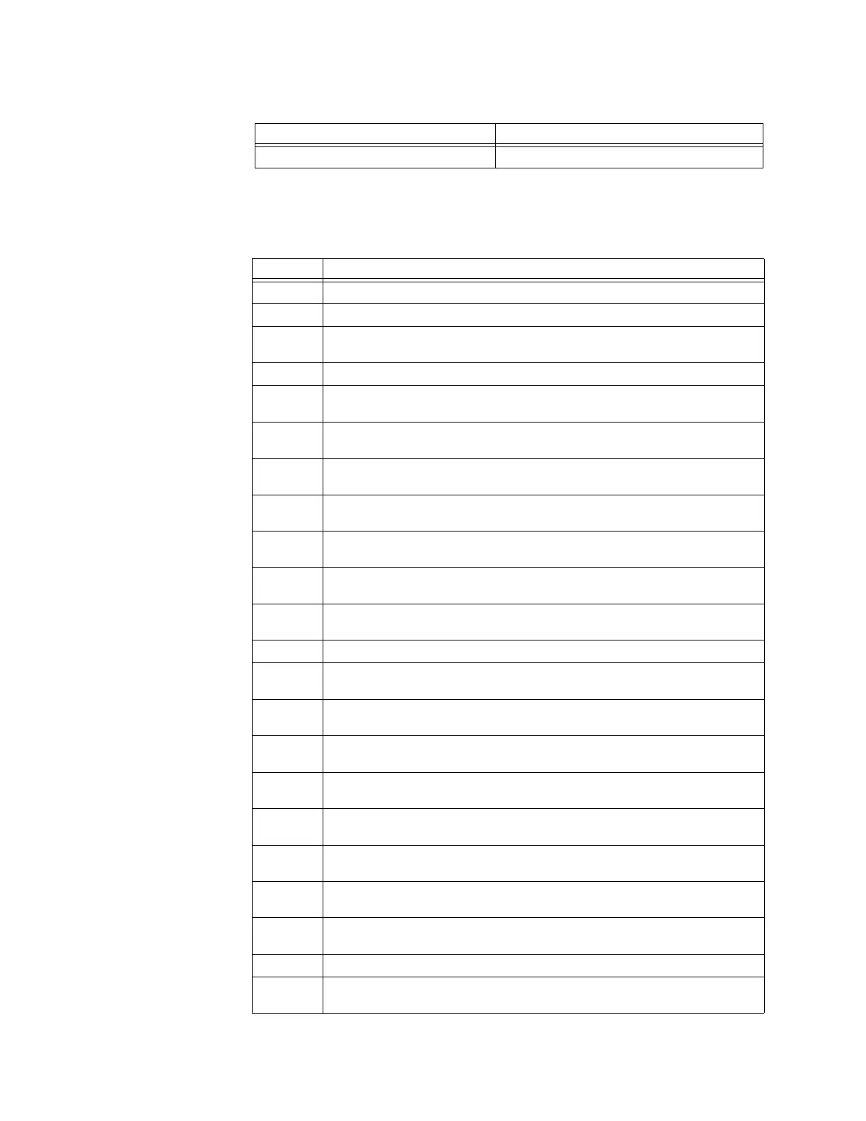
Table A-1: Revision History
MANUAL P/N RELEASE DATE
Table A-2: Major Updates for 850-AB
Chapter SECTION and CHANGES
cover Manual revision number from AA to AB, 850 version updated to 2.0x
1 Added Accessories list to Order Code section
1
Added note to Order Code section: Refer to the online store for available
order code combinations.
2 Added depth-reducing collar installation instructions and dimensions
3
Revised Single Line Diagram section, see Interfaces > Front Panel Interface >
Graphical Display Pages
3
Added new SLD Configurator section see Interfaces> Software Interface >
Advanced EnerVista 8 Series Setup Software Features
4
Added new Tab Pushbuttons section to Setpoints > Device > Front Panel >
Tab Pushbuttons
4
Added new Annunciator with Panel section to Setpoints > Device > Front
Panel > Annunciator
4
Added new Switches section (for disconnect switch setup) to Setpoints >
System > Switches
4
Revised Breaker logic diagram to 892740A2.cdr to update settings for
contact input 52a, 52b and remove the breaker disconnected dependencies
4
Revised Undercurrent logic diagram to 894205A1.cdr to add setting for
signal input
4 Added new SOTF section to Setpoints > Protection
4
Revised Negative Sequence Directional OC logic diagram to 894204A1.cdr to
add setting for signal input
4
Revised Broken Conductor logic diagram to 894043A2.cdr to add setting for
signal input
4
Revised Load Encroachment logic diagram to 894044A2.cdr to add settings
for CT input and VT inputs
4
Revised Thermal Overload logic diagram to 894045A3.cdr to add setting for
signal input
4
Added new Timed Undervoltage section to Setpoints > Protection > Voltage
Elements
4
Added new UV Reactive Power section to Setpoints > Protection > Voltage
Elements
4
Revised Neutral Overvoltage logic diagram to 894050A2.cdr to add setting
for signal input
4
Revised Negative Sequence OV logic diagram to 894051A2.cdr to add
setting for signal input
4 Added new Admittance section to Setpoints > Protection
4
Revised Wattmetric Ground Fault logic diagram to 894053A2.cdr to add
settings for CT and VT inputs

 Loading...