CHAPTER 2: INSTALLATION ELECTRICAL INSTALLATION
850 FEEDER PROTECTION SYSTEM – INSTRUCTION MANUAL 2–13
Terminal Identification
All the terminal strips are labeled with a slot letter to identify the module slot position and
numbers to identify the terminals within the module.
CAUTION:
Make sure that the first letter on the terminal strip corresponds to the slot location
identified on the chassis silkscreen.
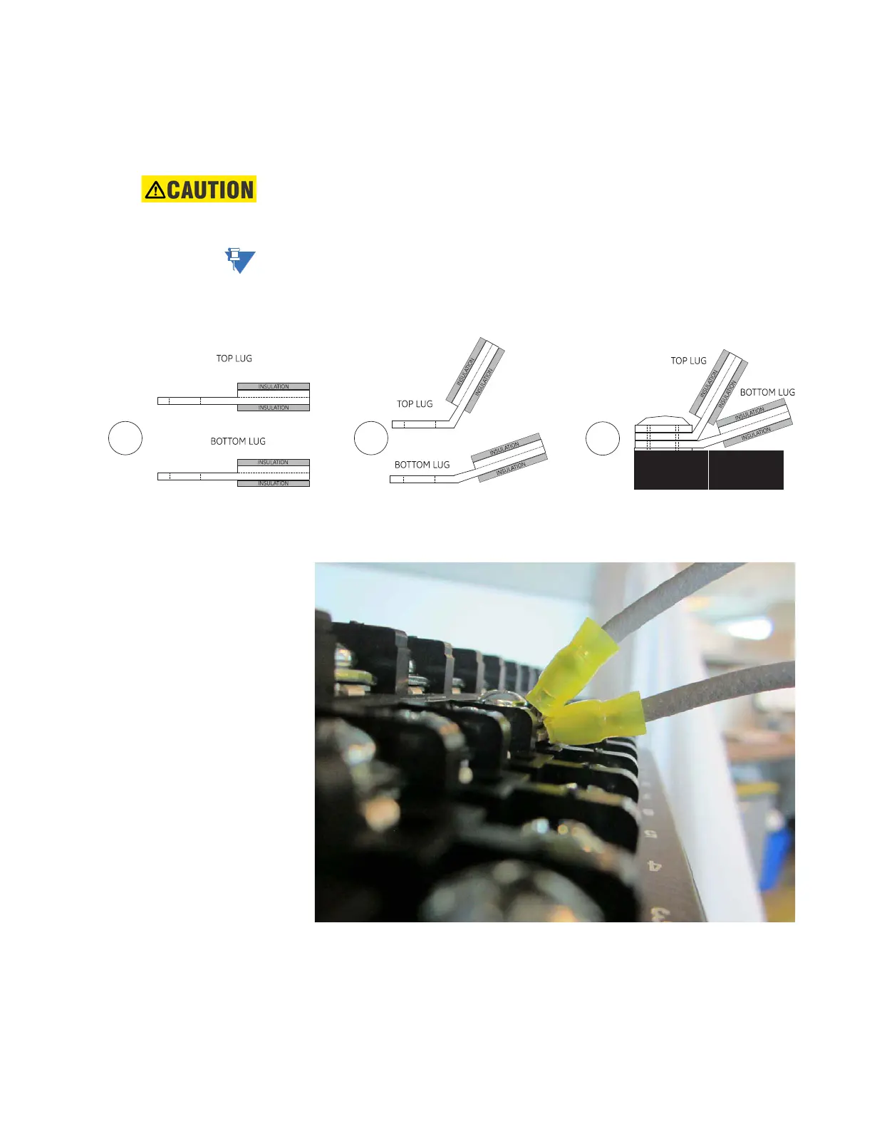
Terminal Connections
NOTE:
When installing two lugs on one terminal, both lugs must be “right side up” as shown in the
picture below. This is to ensure the adjacent lower terminal block does not interfere with
the lug body.
Figure 2-15: Orient the Lugs Correctly
Figure 2-16: Correct Installation Method
SCREW
WASHER
LOWER
TERMINAL
DIVIDER
TERMINAL
BLOCK
1
2
3