CHAPTER 6: METERING POWER
850 FEEDER PROTECTION SYSTEM – INSTRUCTION MANUAL 6–11
Power
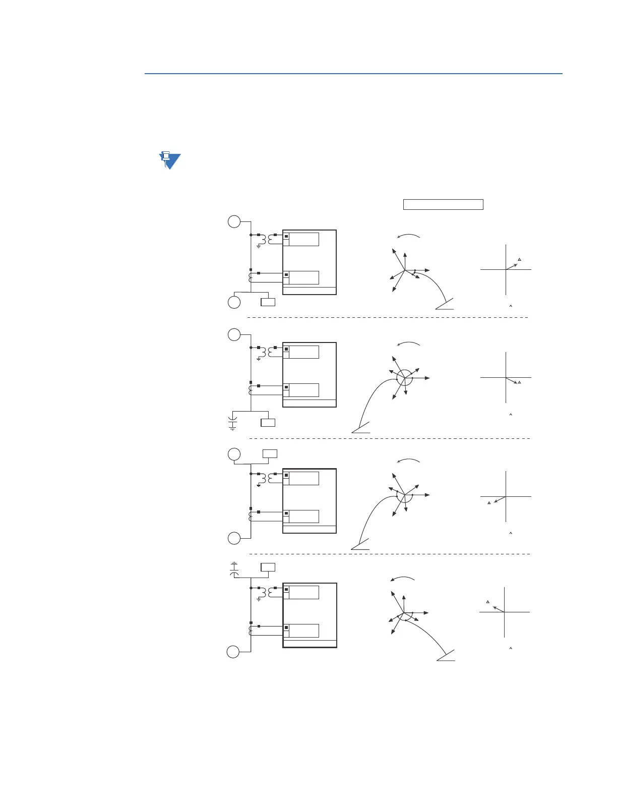
The following figure illustrates the convention used for measuring power and energy in the
8 Series devices.
NOTE:
Power 1 is calculated using 3-phase J1 Currents & 3-phase J2 Voltages. Power 2 is
calculated using 3-phase K1 Currents & 3-phase J2 Voltages.
Figure 6-5: Flow direction of signed values for watts and VARs
Path: Metering > Power 1(X)
Real Total (Real)
Range: - 214748364.8 kW to 214748364.7 kW
PER IEEE CONVENTIONS
Parameters as seen by
the 8-series relays
Voltage
Generator
Generator
Inductive
Inductive Resistive
Resistive
Generator
Generator
8-SERIES IED
G
G
M
M
G
G
VCG
IC
VAG
IA
VBG
IB
VCG
IC
VAG
IA
VBG
IB
VCG
IC
VAG
IA
VBG
IB
VCG
IC
VAG
IA
VBG
IB
+Q
+Q
+Q
+Q
PF = Lead
PF = Lead
PF = Lead
PF = Lead
PF = Lag
PF = Lag
PF = Lag
PF = Lag
PF = Lag
PF = Lag
PF = Lag
PF = Lag
PF = Lead
PF = Lead
PF = Lead
PF = Lead
–Q
–Q
–Q
–Q
–P
–P
–P
–P
+P
+P
+P
+P
IA
IA
IA
IA
S=VI
LOAD
LOAD
Resistive
Resistive
LOAD
LOAD
Watts = Positive
Vars = Positive
PF = Lag
Current
–Θ °
1
Voltage
8-SERIES IED
Watts = Positive
Vars = Negative
PF = Lag
Current
–Θ °
2
S=VI
–Θ °
3
Voltage
8-SERIES IED
Watts = Positive
Vars = Negative
PF = Lag
Current
S=VI
Voltage
8-SERIES IED
Watts = Positive
Vars = Negative
PF = Lag
Current
–Θ °
4
S=VI
894160A1.CDR