CHAPTER 4: SETPOINTS OUTPUTS
850 FEEDER PROTECTION SYSTEM – INSTRUCTION MANUAL 4–105
EVENTS
Range: Disabled, Enabled
Default: Enabled
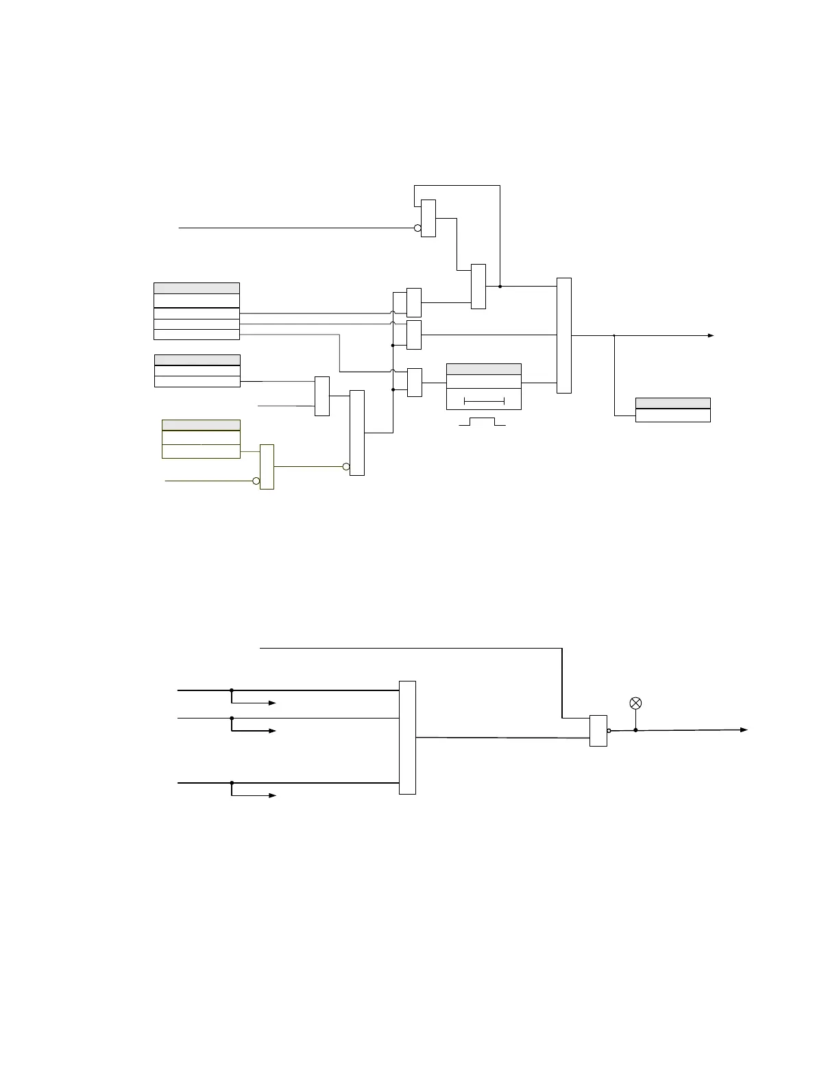
Figure 4-38: Auxiliary Relays generic logic
Critical Failure Relay
#8
The 850 relay is equipped with one output relay (# 8 - “Critical Failure Relay”) for failsafe
indication. The Critical Failure Relay is a Form-C contact with one NO and one NC contact
(no control power). There are no user-programmable setpoints associated with this output
relay. The logic for this relay is shown below.
Figure 4-39: Critical Failure Relay 8 Scheme
892828A3.cdr
AND
SETPOINT
TYPE
Latched
Self-Reset
AND AND
OR
AND
OR
RESET (Command)
Operate Aux Output Relay
Pulsed
AND
SETPOINT
OPERATE
Off = 0 SEAL-IN TIME
SETPOINT
t
This setpoint is displayed only
upon “Pulsed” output type selection
OR
Operation (from Protection,
Control, or Monitoring Elements)
Relay ( Ready = 1)
Relay ( Ready = 1)
OR
BLOCK
SETTING
Off = 0
Relay ( Ready = 1)
Aux Relay X ON
FLEXLOGIC OPERAND
892702A2.cdr
ANY MAJOR ERROR
(Force the Relay into ‘NOT READY’ state)
Setpoint /Device/Installation = Not Ready
Major Error 1
Message & Event Records
OR
OR
LED: IN SERVICE
In Service:
To Output Relays
Major Error
2
Message & Event Records
Major Error xx
Message & Event Records
.
.
.
.