CHAPTER 4: SETPOINTS PROTECTION
850 FEEDER PROTECTION SYSTEM – INSTRUCTION MANUAL 4–185
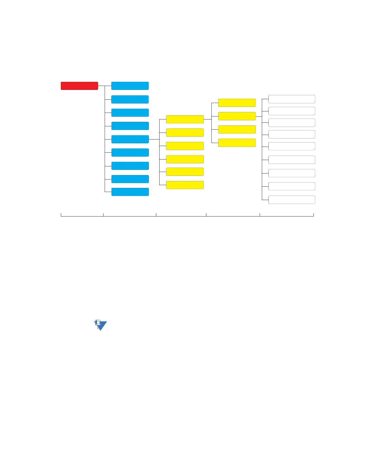
Voltage Elements
Figure 4-73: Voltage Elements Display Hierarchy
Undervoltage Curves The undervoltage elements can be programmed to have an inverse time delay
characteristic. The undervoltage delay setpoint defines a family of curves as shown below.
The operating time is given by:
T = D/(1 - V/V
pkp
)
Where:
T = Operating Time
D = Undervoltage Pickup Time Delay setpoint (for D = 0.00 operates instantaneously)
V = Voltage as a fraction of the nominal VT Secondary Voltage
V
pkp
= Undervoltage Pickup Level
The element resets instantaneously if the applied voltage exceeds the dropout voltage. The
delay setting selects the minimum operating time of the phase undervoltage.
NOTE:
At 0% of Pickup, the operating time equals the Undervoltage Pickup Time Delay setpoint.
Level 1 Level 2 Level 3 Level 4 Level 5
Setpoints
Device
System
Inputs
Outputs
Protection
Monitoring
Control
FlexLogic
Data Capture
Power
Voltage
Current
UV Curves
Neutral OV
Phase OV
Neg Seq OV
Auxiliary OV
Data Capture
Group 1
Group 2
Group 3
Group 4
Group 5
Group 6
Frequency
Phase UV
Auxiliary UV
Testing
Timed UV
UV Reactive Power