2–20 850 FEEDER PROTECTION SYSTEM – INSTRUCTION MANUAL
ELECTRICAL INSTALLATION CHAPTER 2: INSTALLATION
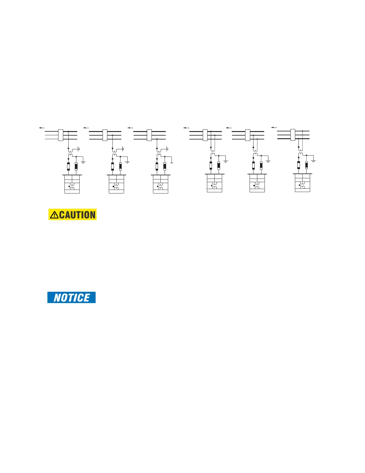
Voltage Inputs
The 850 relays have four channels for AC voltage inputs, each with an isolating
transformer. Voltage transformers up to a maximum 5000:1 ratio may be used. The
nominal secondary voltage must be in the 10 to 240 V range. In Main-Tie-Main bus
transfer scheme, the three phase inputs are mostly used for “Bus voltage”. The Bus VT
connections most commonly used, wye and delta (or open delta), are shown in the typical
wiring diagram. The single Auxiliary voltage input is commonly used as the “line voltage”.
The line VT input channel, used for the synchrocheck feature, can be connected for phase-
neutral voltages V
an
, V
bn
, or V
cn
; or for phase-phase voltages V
ab
, V
bc
, or V
ca
as shown.
Figure 2-22: Line VT Connections
CAUTION:
If Delta VTs are used for three-phase voltages, the zero sequence voltage (V0) and
neutral/sensitive ground polarizing voltage (–V0) are zero. Also, with the Delta VT
connection, the phase-neutral voltage cannot be measured and is not displayed.
Restricted Earth Fault Inputs
Restricted Earth Fault protection is often applied to transformers having grounded Wye
windings to provide ground fault detection for faults near the transformer neutral. Each
current bank on the relay has 3 phase current inputs and one ground input. Any of the
available inputs on the relay current banks can be selected as a signal input for an RGF
element.
FAST PATH:
Although the 850 is designed for feeder protection, it can provide Restricted Earth Fault
protection on transformers that do not have dedicated protection.
The phase and ground input CT connections to the relay are shown below:
892776A3.CDR
TO BUS VTs
A
C
B
J15
AUX
J16
VV
1 2
2
V
1
V
AUX
J15 J16
Van
Vab
52
TO BUS VTs
A
C
B
J15
AUX
J16
VV
1 2
Vbn
52
TO BUS VTs
A
C
B
J15
AUX
J16
VV
1 2
Vcn
52
TO BUS VTs
A
C
B
52
2
V
1
V
AUX
J15 J16
Vbc
TO BUS VTs
A
C
B
52
2
V
1
V
AUX
J15 J16
Vca
TO BUS VTs
A
C
B
52