CHAPTER 2: INSTALLATION ELECTRICAL INSTALLATION
850 FEEDER PROTECTION SYSTEM – INSTRUCTION MANUAL 2–21
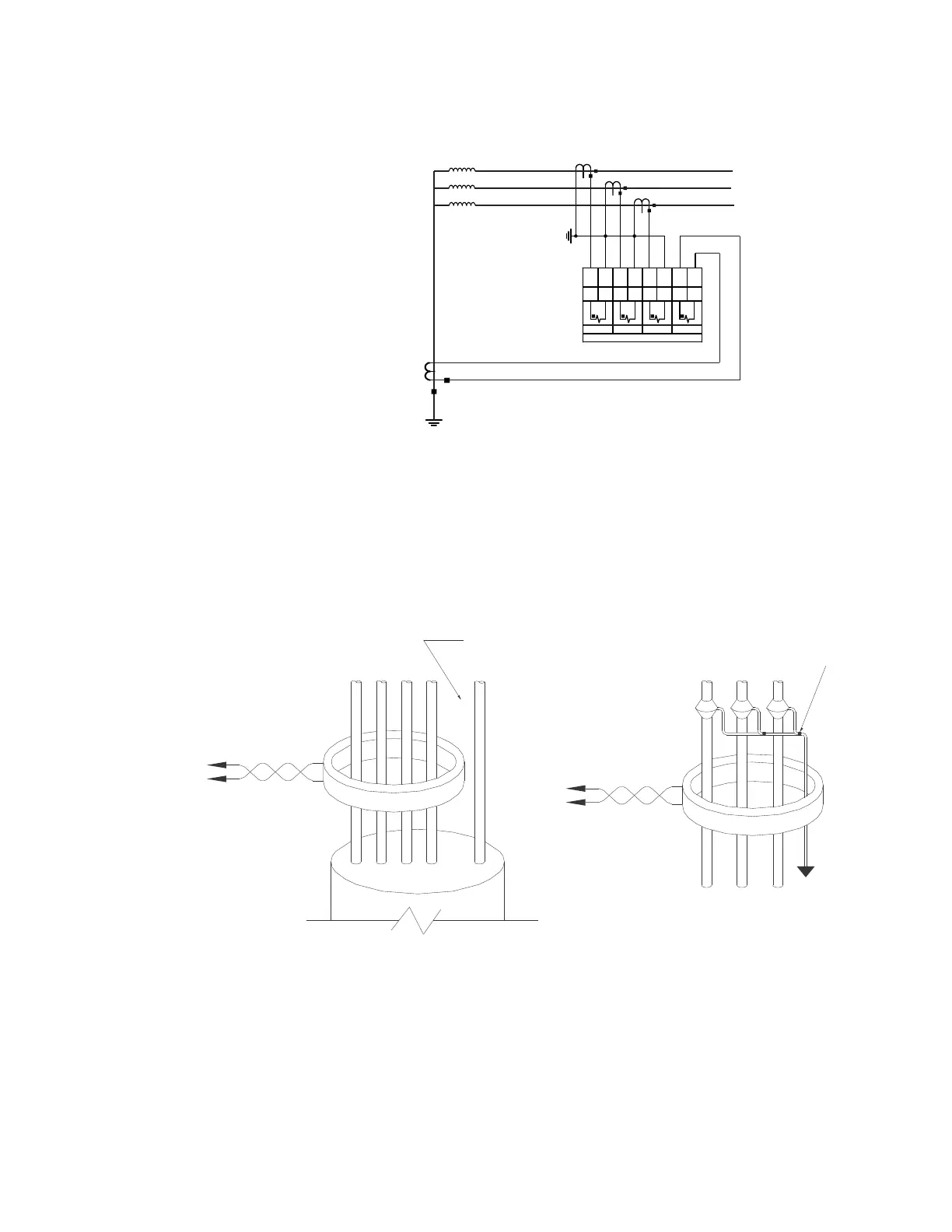
Figure 2-23: Restricted Ground Fault Inputs
Zero-Sequence CT Installation
The figure below shows the various CT connections and the exact placement of a Zero
Sequence current CT, so that ground fault current can be detected. Twisted pair cabling on
the Zero Sequence CT is recommended.
Figure 2-24: Zero Sequence (Core Balance) CT Installation
J1 J2 J3 J4 J5 J6 J7 J8
CURRENT INPUTS
PHASE A PHASE B PHASE C
GROUND
I
A
N
I
C
I
B
I
G
NN
N
FEEDER
TRANSFORMER
892775A1.cdr
Ground connection to neutral
must be on the source side
UNSHIELDED CABLE
LOAD
ABCN G
Ground
outside CT
Source
LOAD
SHIELDED CABLE
996630A5
AB C
Source
To ground;
must be on
load side
Stress cone
shields

 Loading...


