CHAPTER 2: INSTALLATION ELECTRICAL INSTALLATION
850 FEEDER PROTECTION SYSTEM – INSTRUCTION MANUAL 2–17
Table 2-5: AC Analog
Wire Size Use the following guideline when selecting wires or lugs to connect to terminal strips A, B,
C, D, E, F, G, H, and terminal blocks J, K. Note that the first two bullets are applicable to
terminal blocks J and K only:
• 12 AWG to 22 AWG (3.3 mm
2
to 0.3 mm
2
): Single wire termination with/without 9.53
mm (0.375”) maximum diameter ring terminals.
• 14 AWG to 22 AWG (2.1 mm
2
to 0.3 mm
2
): Multiple wire termination with 9.53 mm
(0.375”) maximum diameter ring terminals. Two ring terminals maximum per circuit.
• Suggested wiring screw tightening torques are: terminal strips A-H tighten to 4.5 in-lbs
(0.5 N-m) and terminal blocks J, K to 15 in-lb (1.7 N-m).
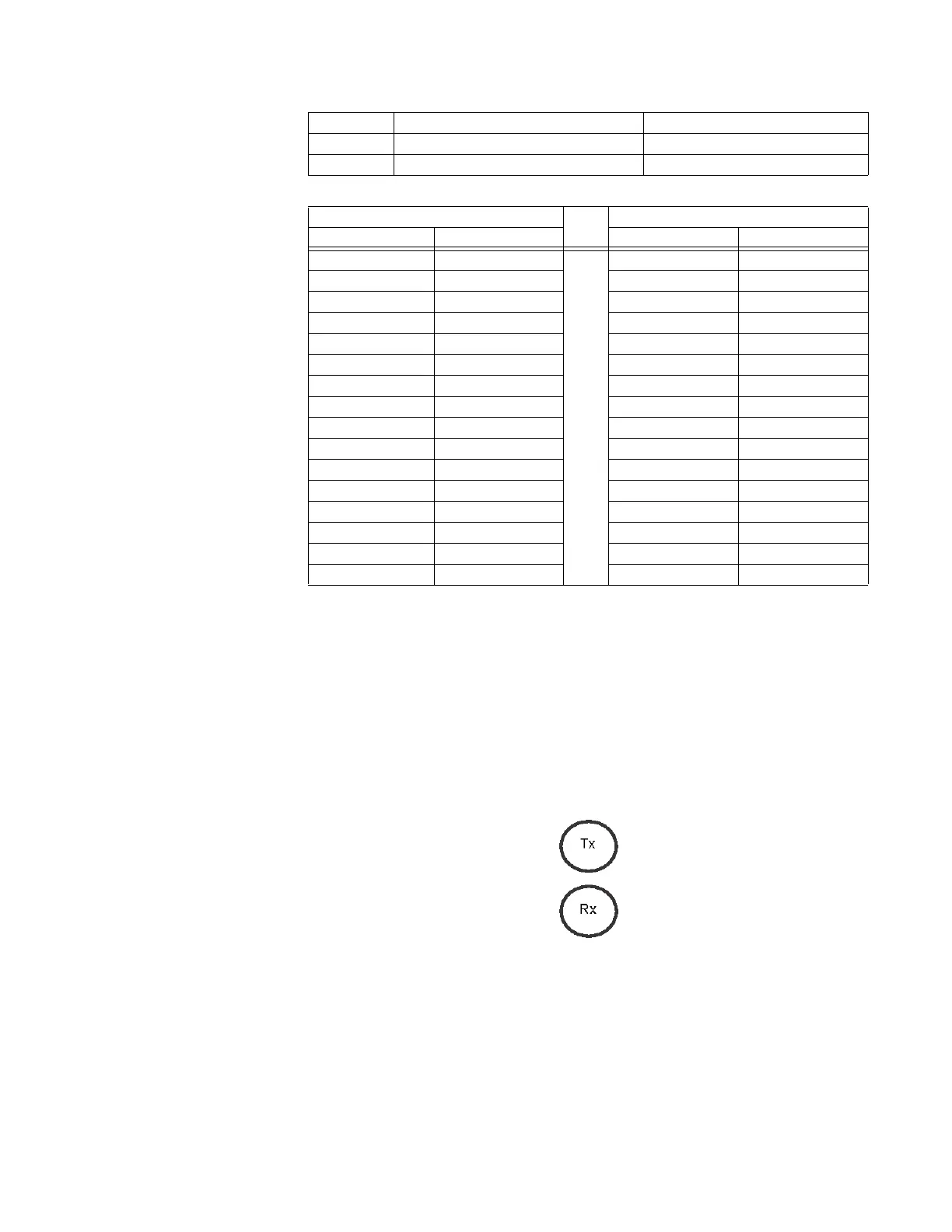
Figure 2-19: Fiber Connector Types (S - ST)
22 FC_3 NC Critical Fail Relay
23 FC_3 COM Critical Fail Relay
24 FC_3 NO Critical Fail Relay
AC Inputs - 4 X 1/5A CT, 4 VT AC Inputs - 1 X 1/5A CT
Terminal Description Terminal Description
1 CT1_IN 1 RESERVED
2 CT1_RETURN 2 RESERVED
3 CT2_IN 3 RESERVED
4 CT2_RETURN 4 RESERVED
5 CT3_IN 5 RESERVED
6 CT3_RETURN 6 RESERVED
7 CT4_IN 7 CT5_IN
8 CT4_RETURN 8 CT5_RETURN
9 VT1_IN 9 RESERVED
10 VT1_RETURN 10 RESERVED
11 VT2_IN 11 RESERVED
12 VT2_RETURN 12 RESERVED
13 VT3_IN 13 RESERVED
14 VT3_RETURN 14 RESERVED
15 VT4_IN 15 RESERVED
16 VT4_RETURN 16 RESERVED