CHAPTER 4: SETPOINTS PROTECTION
850 FEEDER PROTECTION SYSTEM – INSTRUCTION MANUAL 4–195
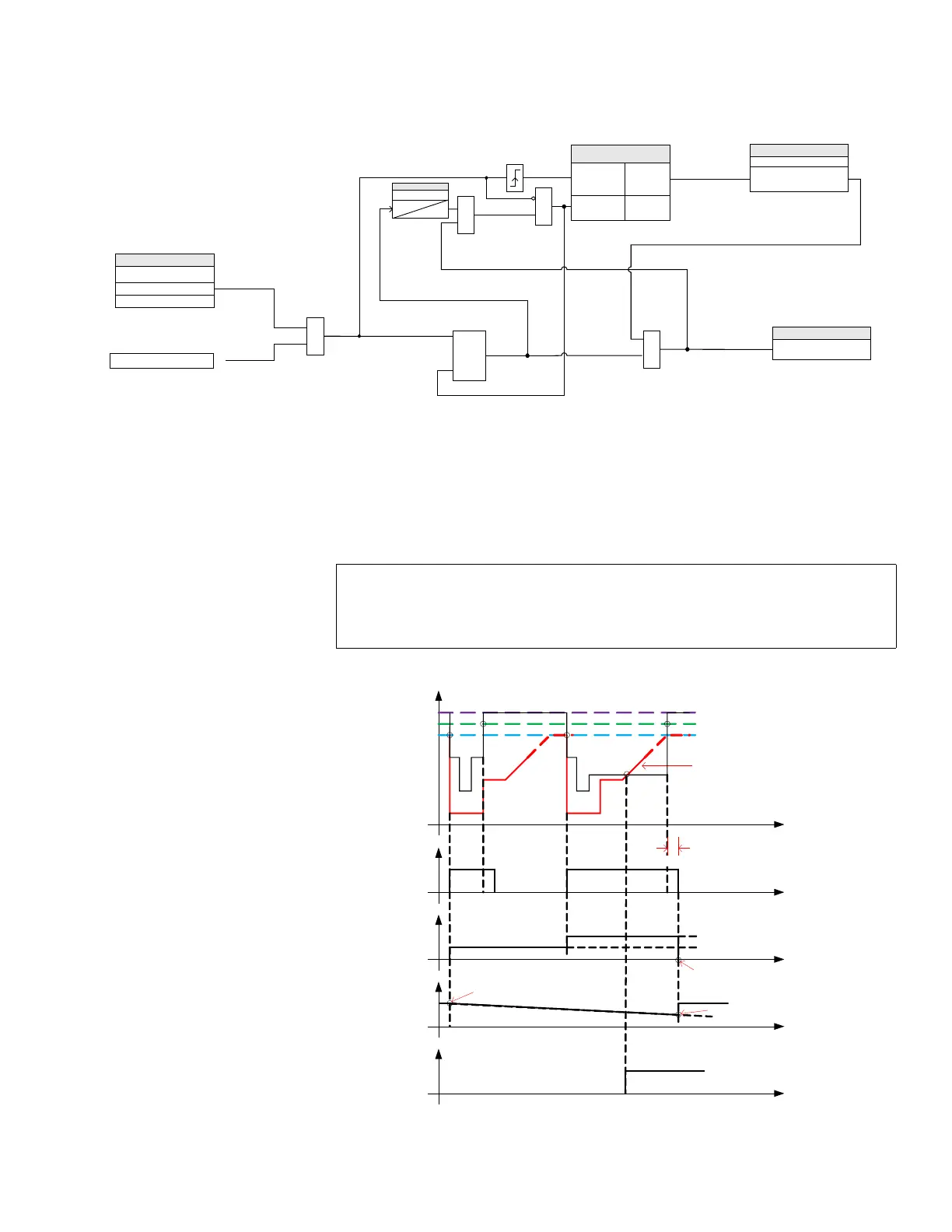
Figure 4-77: Counter Based Timed Undervoltage Protection logic diagram
Logic Explanation for System Scenarios
For the logic shown in the preceding logic diagrams, the sample system scenarios are
explained in Case1, 2, and 3 respectively.
Case 1
Behavior when the element trips by entering the operating region of the configurable
characteristic curve. The element operates due to the trip time defined by the curve. The
sample settings and the expected behavior are shown here.
Figure 4-78: System behaviour from Case 1
894189A1.cdr
A
N
D
SETPOINTS
COUNTER MODE
Enabled
Timed UV 1 PKP
From Timed UV protection
logic diagram
}
Disabled
SET
RST
SETPOINT
Time for Voltage Drops
t
VDrops
0
A
N
D
FlexLogic Operands
Timed UV 1 Cnt OP
Voltage Drop Counter
Increment 1 to 11
Reset 0
O
R
SETPOINTS
VOLTAGE DROPS
Count > Number of Voltage
Drops Allowed
A
N
D
Reset Dominant
Curve Settings: As shown in the red characteristic curve
Pickup: 0.90 x VT
Dropout: 105.5 % of PKP (0.95 x VT)
Voltage Drops: 2
PICKUP
DROPOUT
t
xVT
Vnom
Operating
Characteristic
PKP
dropout delay
Ph UV
Counter
1
2 = threshold
counter reset to 0
TRIP by
Curve
Time
slot for
voltage
drops
timer reset
t
t
t
t
1. 00
0. 95
0. 90
timer started

 Loading...


