4–198 850 FEEDER PROTECTION SYSTEM – INSTRUCTION MANUAL
PROTECTION CHAPTER 4: SETPOINTS
characteristic curve for time-dependent undervoltage protection. If the voltage goes
below the pickup level, the pickup event is issued along with the LED. If the measured
voltage rises above the dropout level before the time for operation is reached, the
element drops out from pickup. If the voltage drop exceeds the time specified by the
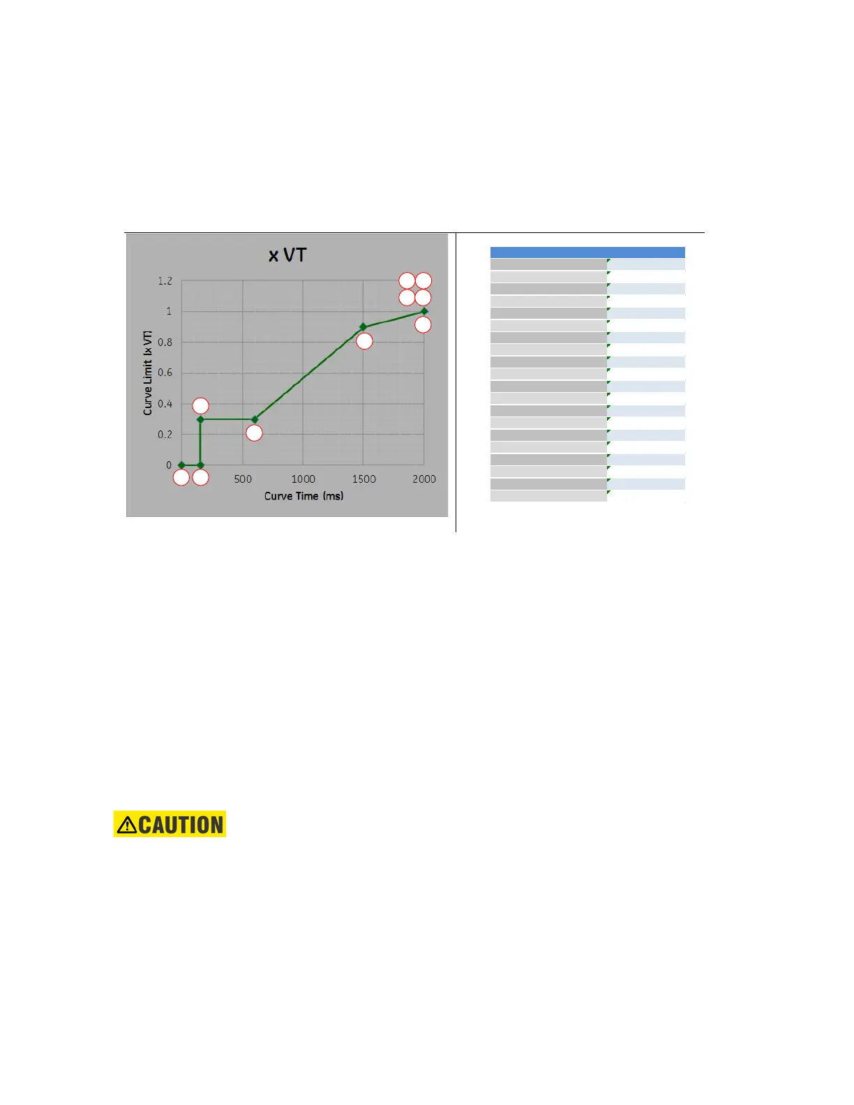
configurable curve, a trip is issued by the timed undervoltage element. The following
figure shows the sample characteristics (C) and the equivalent curve settings (D) for it.
Figure 4-82: Sample LVRT characteristics and Equivalent curve points
Counter based undervoltage protection
The Counter based undervoltage protection works in parallel to the Timed undervoltage
protection. When this mode of protection is enabled, every undervoltage pickup event
increments the counter by one. Simultaneously, a reset-dominant latch is activated with
the timer that counts down the total time for allowed transient voltage drops as
programmed in the Voltage Drops setting. Every subsequent undervoltage pickup event
increments the counter by one as long as the Time for Voltage Drops time is active. If the
number of voltage drops exceeds the programmed threshold value before the total time
allowed for voltage drop expires, a trip (Timed UV 1 Cnt OP) is issued.
The counter and timer are both reset if there is no timed undervoltage pickup and one of
these two conditions occurs:
1. A trip signal is issued due to the counter exceeding the programmed threshold for the
number of voltage drops
2. Total time for allowed voltage drop expires without reaching the programmed
threshold for number of voltage drops
CAUTION:
The curve time needs to be set to progressively increasing. If the curve times are not
set to progressively increasing, the points are sorted by time and that new sorted
curve is used. If the curve limits are not set to progressively increasing, there is a
possibility of having multiple operating points. In this case, the lower timed operating
point will be put ahead of the higher operating time and the lower timed operating
point is used for operation.
1 2
3
4
5
6
7 8
9 10
(C) Sample LVRT Characteristics
(D) Equivalent Curve Points
Item Name Value Unit
Curve Limit 1 0.00 x VT
Curve Time 1 0.000 s
Curve Limit 2 0.00 x VT
Curve Time 2 0.150 s
Curve Limit 3 0.30 x VT
Curve Time 3 0.150 s
Curve Limit 4 0.30 x VT
Curve Time 4 0.600 s
Curve Limit 5 0.90 x VT
Curve Time 5 1.500 s
Curve Limit 6 1.00 x VT
Curve Time 6 2.000 s
Curve Limit 7 1.00 x VT
Curve Time 7 2.000 s
Curve Limit 8 1.00 x VT
Curve Time 8 2.000 s
Curve Limit 9 1.00 x VT
Curve Time 9 2.000 s
Curve Limit 10 1.00 x VT
Curve Time 10 2.000 s