CHAPTER 4: SETPOINTS PROTECTION
850 FEEDER PROTECTION SYSTEM – INSTRUCTION MANUAL 4–201
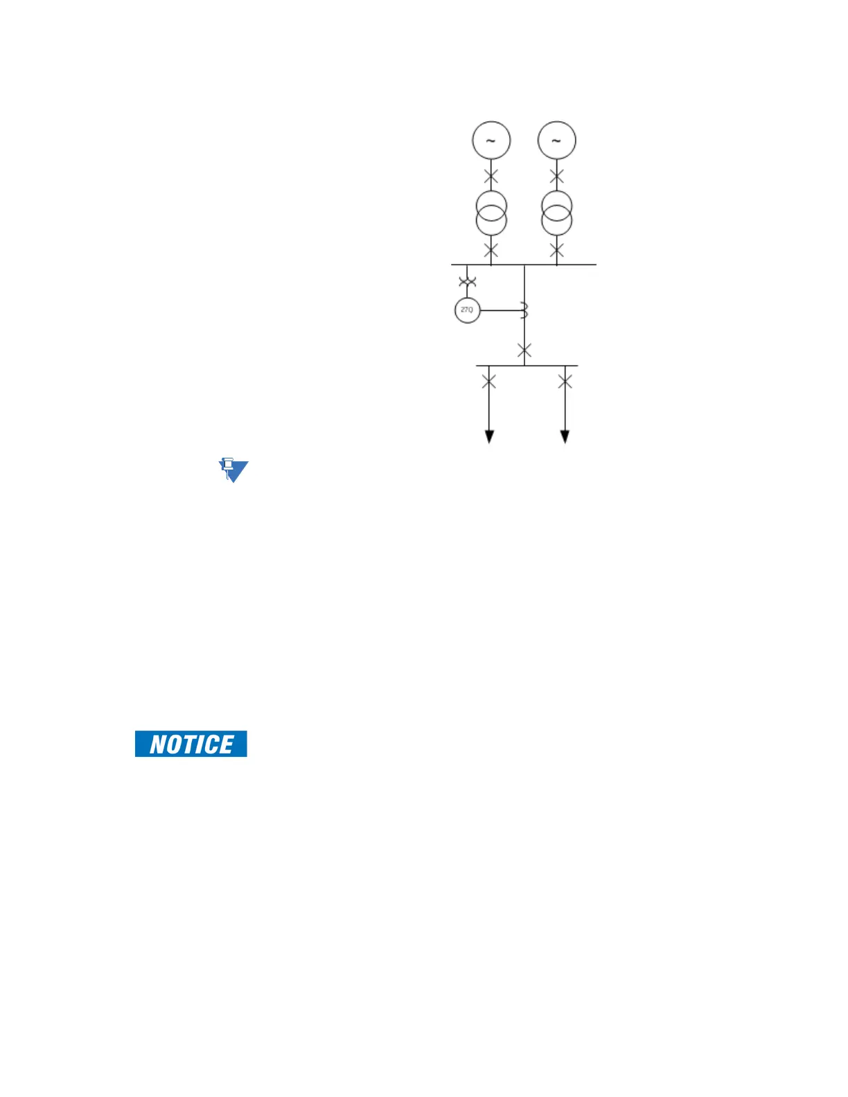
Figure 4-84: Example of UV Reactive Power (27Q) applied for the generating feeder
NOTE:
UV Reactive Power 1 (2 or 3) are associated with Breaker 1 and UV Reactive Power 4 (5 or 6)
are associated with Breaker 2. When the restoration function is enabled, respective closing
relays are used depending on the UV Reactive Power element instance.
Path: Setpoints > Protection > Group 1(6) > Voltage > UV Reactive Power 1(X)
FUNCTION
Range: Disabled, Trip, Alarm, Latched Alarm, Configurable
Default: Disabled
This setting provides the selection for the Phase to ground and Phase to phase voltages
for a Wye VT connection (phase to phase for delta connected VT connection.
VOLTAGE MODE
Range: Phase-ground, Phase-phase
Default: Phase-phase
This setting provides selections for Phase to ground and Phase to phase voltages for a
Wye VT connection (phase to phase for delta connected VT connection).
FAST PATH:
Setpoint Voltage Mode is only applicable when Phase VT Connection (under System/
Voltage Sensing/Ph VT Bnk1-J2) selection is Wye. This setting is hidden when the Phase VT
Connection selection is Delta.
PICKUP VOLTAGE
Range: 0.00 to 1.50 x VT in steps 0.01
Default: 0.85 x VT
This setting specifies the phase undervoltage pickup level specified per times VT.
For example, a Pickup setting of 0.85 x VT with 13800:115 VT translates into 11.730kV (or
97.5V secondary).
If the Voltage Mode selection is Phase-phase and the Phase VT Connection (under
System/Voltage Sensing/Ph VT Bnk1-J2) selection is Wye, the previous example will
translate to the phase-phase voltage value of 11.730kV x 1.732 = 20.31kV