4–222 850 FEEDER PROTECTION SYSTEM – INSTRUCTION MANUAL
PROTECTION CHAPTER 4: SETPOINTS
MODE
Range: Y0, G0, B0
Default: Y0
This setting selects the protection criterion (characteristic quantity) of the Neutral
Admittance Ground Fault protection. When this value is set to Y0, G0 and B0, the
protection criterion is Neutral-Admittance, Neutral-Conductance, and Neutral-
Susceptance, respectively.
DIRECTION
Range: Non-directional, Forward, Reverse
Default: Non-directional
When set to “Non-Directional”, the element operates in both forward and reverse
direction. If set to “Forward”, the element operates when the fault is detected in the
forward direction. When set to “Reverse”, the element operates when the fault is
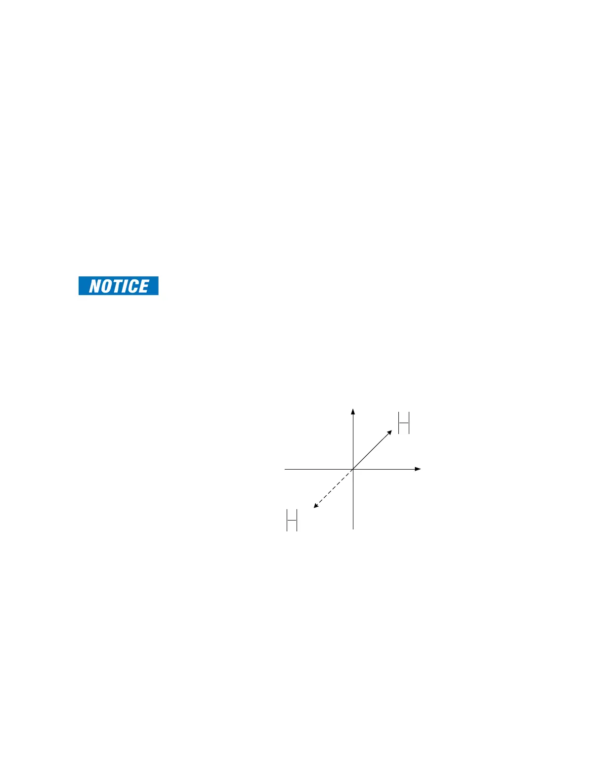
detected in the Reverse direction.The following figures show the interactions between
different setting options of the parameters Mode and Direction per the tripping and
operating ranges of the Neutral Admittance Ground Fault protection.
FAST PATH:
This is setting is not applicable to protection criterion mode Y0.
ANGLE CORRECTION
Range: 0.0 to 359.0° in steps of 0.1°
Default: 0.0°
This setting specifies the correction angle between current and voltage.
In addition, this setting can be used to correct the relative polarity of the ground current
with respect to voltage. If the polarity of the current is reversed or not relative to voltage,
this setting can be used to change the polarity. When “180 deg” is selected, the
measured admittance Y0 is multiplied with -1 which corresponds to a 180 degree shift in
current direction.
)(
00
0
0
0
VI
V
I
Y
)( 180
00
0
0
0
VI
V
I
Y

 Loading...


