CHAPTER 4: SETPOINTS MONITORING
850 FEEDER PROTECTION SYSTEM – INSTRUCTION MANUAL 4–269
the supervision conditions, the power factor will be re-calculated based on the still valid
phase(s). If the element is continuously asserted with the new power factor value, the timer
will continue timing, otherwise, the element will reset without operating.
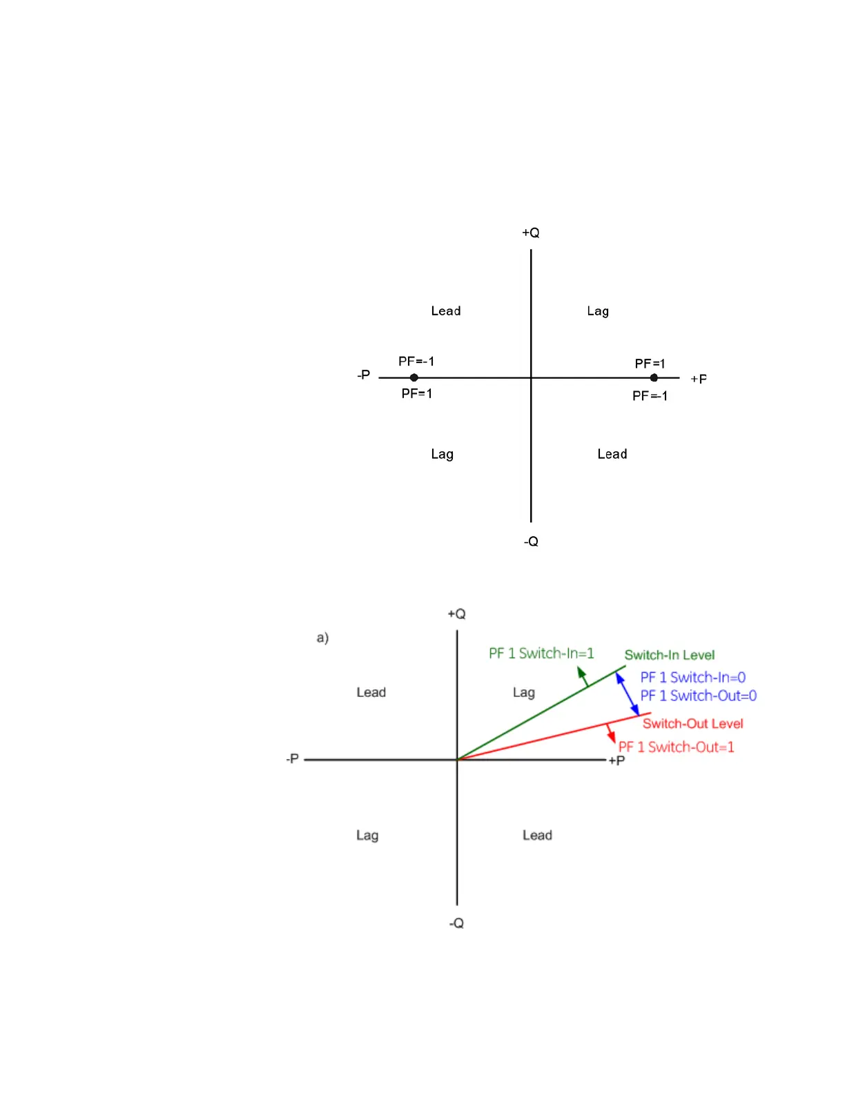
The following figure illustrates the conventions established for use in 850 relays, where the
negative value means the lead power factor, and the positive value means the lag power
factor.
Figure 4-117: Conventions for Power Factor
For example, the applications of Switch-In and Switch-Out levels are shown in the figures
below.
 Loading...


